M12 Hardware Design
M12_Hardware_Design_V3.3 - 58 -
3.14. Operating status indication
The STATUS pin is set as an output pin and can be used to judge whether module is power-on,
please refer to Section 3.4. In customer design, this pin can be connected to a GPIO of DTE or be
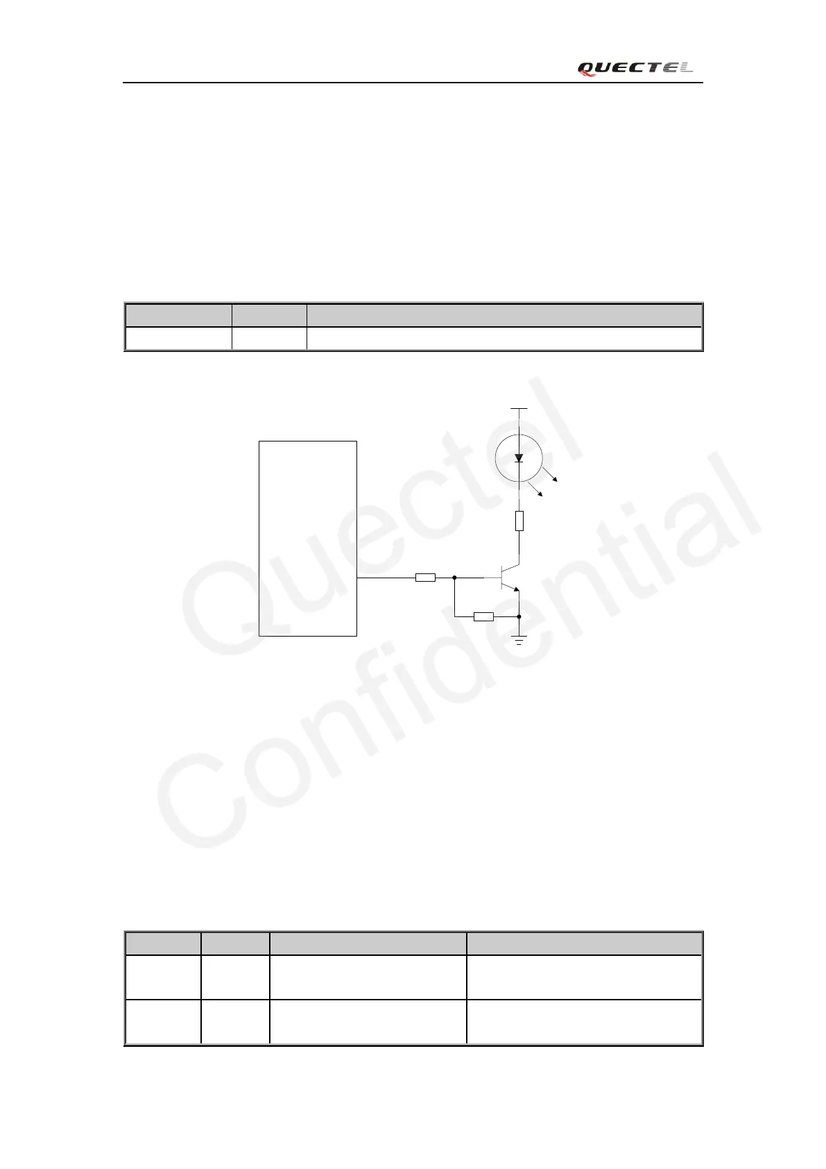
used to drive an LED in order to judge the module’s operation status. A reference circuit is shown
in Figure 42.
Table 20: Pin definition of the STATUS
Module
STATUS
4.7K
47K
300R
VBAT
Figure 42: Reference circuit of the STATUS
3.15. General purpose input & output (GPIO)
The module provides a limited number of General Purpose Input/Output signal pins. The driving
capability of these pins is 4mA. Every GPIO can be configured as input or output by AT
command. For details, please refer to document [1].
Table 21: Pin definition of the GPIO interface
Indicate module’s operating status
Pulled up internally to 75K
resistor
General Purpose Input/Output Port
Pulled up internally
to 75K resistor
General Purpose Input/Output Port