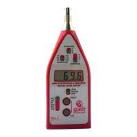
• RT - In the RT mode the display shows the elapsed time of the current or
last RUN. The RT mode consists of two or three displays. The first is RUN
TIME seconds ':XX'. The second is RUN TIME hours/minutes 'XX:XX'.
Pressing the CAL button while in the RT mode toggles the meter between
these two displays. If the RUN TIME exceeds 20 hours, there will be a third
display that will show hours up to 99 'h:XX'. If no RUN time has been
accumulated the display shows dashes.
• MAX - In the MAX mode the display holds the highest reading
encountered during the RUN period. If no RUN time has been accumulated
the display shows dashes.
• MIN - In the MIN mode the display holds the lowest reading encountered
during the RUN period. If no RUN time has been accumulated the display
shows dashes.
• %OL - In the %OL mode the display shows the time that the circuitry has
been overloaded as a percent of RUN TIME. If no RUN time has been
accumulated the display shows dashes.
2.2.3 FAST/SLOW/PEAK/IMP Response Switch:
The Response Switch controls the rate at which the meter responds to
changing input signals. Most sound measurements are done with the
response set to SLOW (S). The FAST (F) response is generally used when
measuring short duration noises such as moving vehicles. PEAK (P) is
useful when measuring the absolute peak of the sound pressure wave.
IMPULSE (I) is used for impulsive or transient sounds.
The Response switch positions are as follows:
• FAST (F) - 125 millisecond time constant. (See Figure 10) Decay Rate =
34.7 dB per second.
• SLOW (S) - 1 second time constant. (See Figure 11) Decay Rate = 4.35
dB per second.
• PEAK (P) - 50 microsecond time constant.
• IMPULSE (I) - 35 millisecond rise time constant, 1.5 second decay time
constant. (See Figure 12)
2.2.4 A/C/Z Switch:
The A/C/Z switch controls the frequency response (weighting) of all
measurements. (See Figure 9)
2.2.5 RANGE (dB) Switch:
The displayed range of the model 1200 is 70 dB and is switchable between
(30-100dB),(50-120dB), and (70-140 dB). After switching ranges allow
several seconds for the meter electronics to stabilize. If a range change is
necessary during a LEQ study, it is good practice to first set the meter to
LEQ PAUSE, change range and then set the meter to RUN. This will avoid
integrating any handling or switching noise into the LEQ measurement.
2.2.6 RESET Button:
This button is used primarily to clear data from the memory of the
instrument. When pressed, the display will begin to count down from '02'. If
the button is pressed and held, the display will count down '02,01, ---'. When
the dashes are displayed the instrument memory is clear.
This button is also used as an up-arrow during setup, (see Operating
Procedure)
2.2.7 CAL Button:
This button has three functions; It initiates a calibration, toggles between Run
Time displays, and acts as a down arrow during setup, (see Operating
Procedure)

 Loading...