22 FUM5-00AM-DES-G5521 V2.1 / 06.06.2019
EN - Operating and Installation Instructions Q gateway 5.5 direct
Mounting point requirements:
0DNHVXUHWKHUHLVDVXႈFLHQWO\VWURQJ*608076VLJQDODWWKHPRXQWLQJSRLQW
The GSM/UMTS signal strength can be determined at the gateway via the control menu, using the *6080760RQLWRUIXQFWLRQ
VHH6HFWLRQ³&RQWUROPHQX´RQSDJH,IWKH*608076VLJQDOLVWRRORZZKLOHWKHJDWHZD\LVRSHUDWLQJÄ/RZ6LJ³DS-
pears on the display. Move the Q gateway 5.5 direct to a location with a better GSM/UMTS signal and repeat the process.
,IGXULQJWKHQHWZRUNVFDQWKHGLVSOD\RIWKHUDGLRVLJQDOVWUHQJWKLQGLFDWHVWKHVLJQDOOHYHOLVWRRORZFKDQJHWKHSRVLWLRQZLWKLQ
the building and repeat the procedure.
7KHGLVSOD\RIWKHUDGLRVLJQDOVWUHQJWKFDQDOVREHGHWHUPLQHGDWWKHJDWHZD\RႉLQHZLWKRXWOLQNWRWKHQ SMPYLDWKH&RQWURO
menu using the ScanIXQFWLRQVHH6HFWLRQ³&RQWUROPHQX´RQSDJH
The following tools are necessary for correct mounting:
• 6WUDLJKWVORWVFUHZGULYHUIRUVLPSOHRSHQLQJRIWKHKRXVLQJFRYHU
• Cross-slot screwdriver or cordless screwdriver
• PPVWRQHGULOOIRUGULOOLQJWKHSOXJKROHVPPLQWKHZDOO
• In addition for Q gateway 5.5 direct RNG5000T1x: 3UHLQVWDOOHGPDLQVFRQQHFWLRQ9$&+]
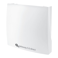
Before wall mounting
• Open the housing cover.
• Plug the battery connector into the power supply connector
6
.
$IWHUFRQQHFWLRQWRWKHSRZHUVXSSO\4JDWHZD\GLUHFWDQLQLWLDOL]DWLRQSURFHVV
is started. The green LED
5
ÀDVKHV
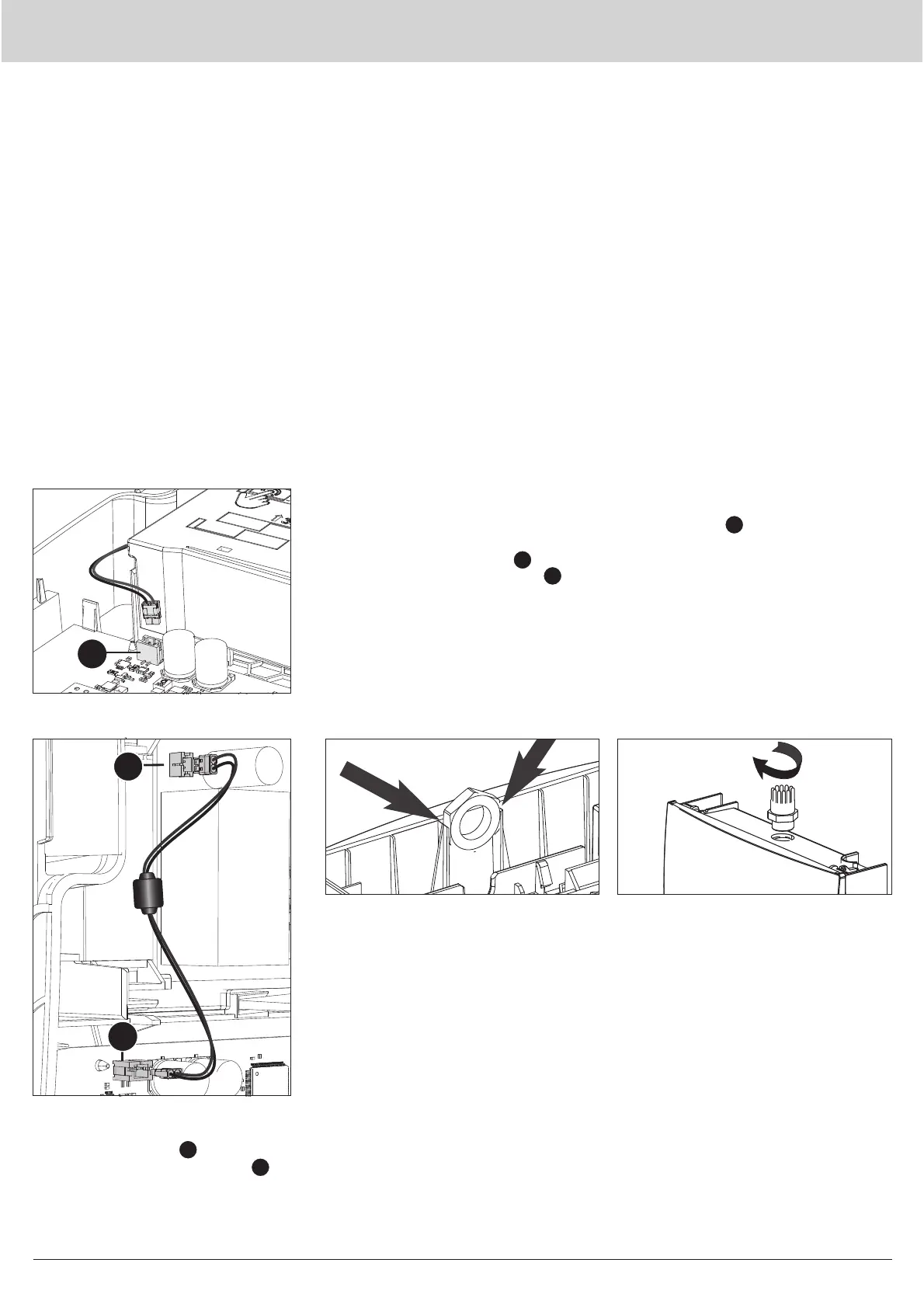
• Close the battery compartment
7
.
• Screw the enclosed cable gland
IURPWKHRXWVLGHWKURXJKWKH
through-hole on the KRXVLQJRIWKH
Q gateway 5.5 direct.
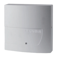
RNG5000T1x only
• Open the housing cover.
• &RQQHFWWKHSOXJFRQQHFWRURIWKH
power supply board
14
with the plug
FRQQHFWRUIRUWKHSRZHUVXSSO\
6
on
the main board using the enclosed
mains connection cable.
• Insert the enclosed hexagon nut IURP
the inside in IURQWRIWKHWKURXJKKROHRQ
the KRXVLQJRIWKH4JDWHZD\GLUHFW.
To do this, push the nut into the guide
UDLODVIDUDVLWZLOOJR
RNG5000T1x only
6
14
6
 Loading...