Do you have a question about the QUNDIS Qheat5 and is the answer not in the manual?
Covers intended use, warranty, and measuring device data plausibility.
Details handling, torque, glycol, and lithium battery safety.
Lists conformity, protection rating, and relevant standards.
Covers MID, EC-type certificate, heat medium, influencing quantities, and calculator unit details.
Details dimensions, flow rates, ratios, start-up, and pressure.
Covers measuring element, diameter, installation type, and cable length.
Provides technical data for connection cables, including color assignment.
Details impulse input device classification and impulse output types.
Shows length and connection cable diagrams with dimensions.
Presents detailed dimensions for the 80 mm heat meter variant.
Presents detailed dimensions for the 110 mm heat meter variant.
Presents detailed dimensions for the 130 mm heat meter variant.
Shows side and front views with dimensions for the 80 mm variant.
Shows side and front views with dimensions for the 110 mm variant.
Shows side and front views with dimensions for the 130 mm variant.
Advises on cable routing, hot water risks, and fitting by experts.
Illustrates permitted installation orientations and forbids overhead mounting.
Shows installation with supply and return sensors for longer models.
Shows installation with supply sensor and separate return sensor for 80mm model.
Shows installation with immersion sleeves for supply and return sensors.
Shows installation with immersion sleeves for supply sensor and separate return sensor.
Details system flushing, valve closing, and specific ball valve use.
Covers removing old parts, seals, and fitting the new meter correctly.
Step-by-step guide for installing 5.0/5.2mm sensors in ball valves.
Visual guide on how to check correct temperature sensor fitting.
Instructions for installing AGFW type temperature sensors with torque values.
Details system flushing, valve closing, and using muffs with immersion sleeves.
Covers removing old parts, seals, and fitting the meter for immersion sleeve installation.
Notes regulations and provides steps for fitting sensors into immersion sleeves.
Instructions for mounting the wall bracket and attaching the calculator unit.
Guides on opening valves, checking flow direction and leak tightness.
Step-by-step process for sealing flow sensors and temperature sensors in ball valves.
Covers sealing immersion sleeve sensors and recording meter data.
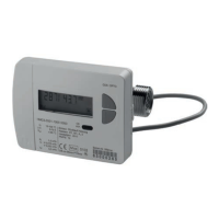
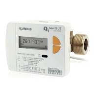
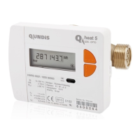
Identifies components and explains various status indicators on the display.
Describes special operating states and lists common error codes with remedies.
Instructions for moving through display levels and key assignment in programming.
Guides on entering programming mode and setting the 'due date' parameter.
Shows how to activate levels and switch the checksum display on/off.
Demonstrates changing the energy unit (kWh/MWh or MJ/GJ) via the interface.
Illustrates recommended installation locations in primary and secondary circuits.
Lists essential checks for security, kits, system flushing, and components.
Verifies sensor installation, valve status, leak tightness, and plausible readings.
Confirms sealing, device number, and initial meter status recording.
Notes compatibility issues and explains serial number interpretation for add-on modules.
Details serial number interpretation for radio and M-Bus modules.
| Mounting | Wall-mounted |
|---|---|
| Power source | Battery |
| Radio frequency | 868 MHz |
| Housing Material | Plastic |
| Temperature Measurement Range | 5°C to 40°C |
| Battery Life | 10 years |
| Communication | Wireless M-Bus |