31
Operation and display
Key assignment in standard mode
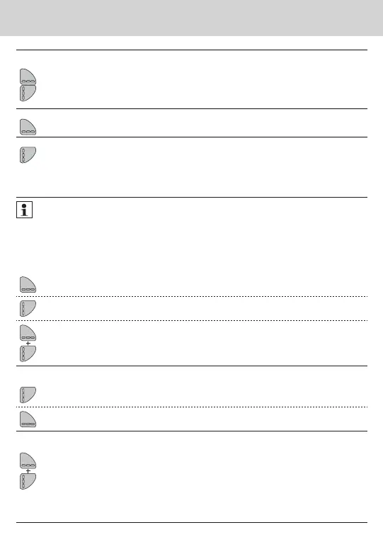
1. To activate the LC display
Press the < H > key or
Press the < V > key
2. To change from any position on one level to the next level
Press the < H > key
3. To change to the next display within one level
Press the < V > key
Navigating within the levels
1. To open the display loop or level operating scheme
Press the < H > or < V > key briefl y to open the fast readout
display loop.
Press the < H > or < V > key longer than 3 seconds to open
the level operating scheme.
2. To change from any position on one level to the next level
Press the < H > key
3. To change to the next display within one level
Press the < V > key
Key assignment in programming mode
To be able to activate programming mode, you have to be authorised for programming
by entering a PIN.
The default standard PIN is printed on the device packaging.
Once the PIN has been accepted, further values can be programmed without PIN input. Va-
lidity is lost if a level other than L3 or L4 is set.
1. To activate programming mode
Use the < H > key to navigate to the level.
Use the < V > key to navigate within the level and
display the value for which the parameter is to be set.
First press and hold the < H > key,
then press and hold the < V > key as well.
2. To change parameters
Press the < V > key briey several times until the parameter sec-
tion ashing has reached the desired value.
Press the < H > key briey to jump to the next
parameter section.
3. To conrm entry
First press and hold the < H > key,
then press and hold the < V > key as well.
(level L3 or L4 only)
Special operating states
Display Description Measures/Notes
• Communication credit
of the module interface
or IrDA exceeded
• Is eliminated after the credit period
(module = current day; IrDA = current
month) has passed.
• Operating time
expired
• Device must be replaced
• Wrong direction of ow • Check installation
(note arrow on ow sensor)
• Check piping
• Check recirculating pumps and thermo-
stats for correct function
• Temperature sensors
have been mixed up or
tted incorrectly
• Check whether ow sensor has been
tted in the right strand or
• check type of installation of temperature
sensor
Error messages
Error display Error description Measures/Notes
• Hardware error or
damaged rmware
• Check ow sensor, connection ca-
ble and calculator unit for external
damage
• Device must be replaced
• Add-on module has
been paired with an-
other meter before
• The module has the measuring data
of another heat meter
• Save data, since these are overwrit-
ten after a short time
• Press any key to delete the display
• Supply ow
sensor broken
• Check temperature sensor and pipes
for mechanical damage
• Device must be replaced
• Short circuit
supply ow sensor
• Check temperature sensor and pipes
for mechanical damage
• Device must be replaced
• Return ow
sensor broken
• Check temperature sensor and pipes
for mechanical damage
• Device must be replaced
• Short circuit
return ow sensor
• Check temperature sensor and pipes
for mechanical damage
• Device must be replaced
Error code Error date
alt.
alt.
alt.
Wrong direction of ow
If a serious error occurs with the device, the
error code and error date are displayed in the
display loop.
If the incorrect direction of ow is established,
the message “Flo.-dir.” appears on the display.
 Loading...