Bubble‐Up®JrInteractive™RadonRemovalSystem
10
Importantinformationaboutventing:SincetheBubble‐Up®JrInteractive™unitremovesradoninthewater;theunit
mustbeventedcarefully.Commonpracticeistoruntheventuppasttherooflineofthebuilding.Anelevatedvent
openingprovidesthebestwayofdissipatingtheradongas.Protocols
recommendextendingtheventopening2’above
thehighestopeninginthebuilding,andatleast10’awayfromthenearestopening.Itisrecommendedtoprotectthe
ventopeningwithaventscreen.Asinglefreehard(printed)copyoftheASTME‐2121standard(Recommended
ResidentialRadonMitigation
StandardofPractice)isavailablefromEPA’sNationalServiceCenterforEn vironmental
Publications(NSCEP).Youcanordera copybyphoneat1‐800‐490‐9198,viaE‐mailnscep@bps‐lmit.com,orviathe
internetatwww.epa.gov/nscep/ordering.htm PleaseusetheEPAdocumentnumber(402‐K‐03‐007)whenorderingE‐
2121.
EPAreprintsE‐2121underagreementwithASTMInternational.
17. Plumbthemechanicalpumpcontrolandplugpumpcordintolowwaterpiggy‐backfloatcord.Plugthelow
waterpiggy‐backfloatcordintothefemalecordofpumpcontrol.SeeFigure7.
18. Checkallplumbingfittingsto
besureallfittingsarewatertight.
19. Thewateralarmvalvecontroliswiredtothepowersupply,motorizedballvalve,andwatersensorterminal
block.
20. Install9Vbatterybackupintowateralarmcontrol.
21. Terminalblockwiresareconnectedtohighwateralarmvalvecontrol,wateralarm
floatswitchandwateralarm
floorsensor.Thesewiresaretwistedtogetherandconnectedtoterminalblock.
Note:WaterSensorTerminalBlockConnection:Connectthewateralarmfloatwire,wateralarmcontrol(figure6),and
wateralarmsensorwirestotheterminalblock(Theterminalblockislocatednexttothe
airvent,figure7).Connectone
wiretotheblackconnectionoftheterminalblockandtheotherwiretotheredconnectionoftheterminalblock.Itis
veryimportantthatthisisagoodconnection.
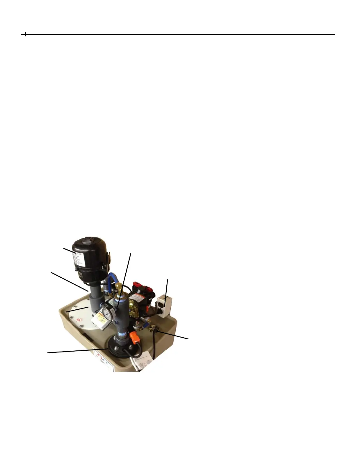
Figure6‐InstallationPoints
AirWaterCou
lin
PumpAccess
WellSeal
Bubble‐U
Blower
2”BlowerAttachment
Ni
le
MechanicalPum
Control
PlugBlowerandSolenoid
intotheDu
lexOutlet
LowWaterPiggy‐Back
FloatCordandHigh
WaterAlarmFloatin
thecordseal