28 Wildcat (BL2000)
3.6 D/A Converter Outputs
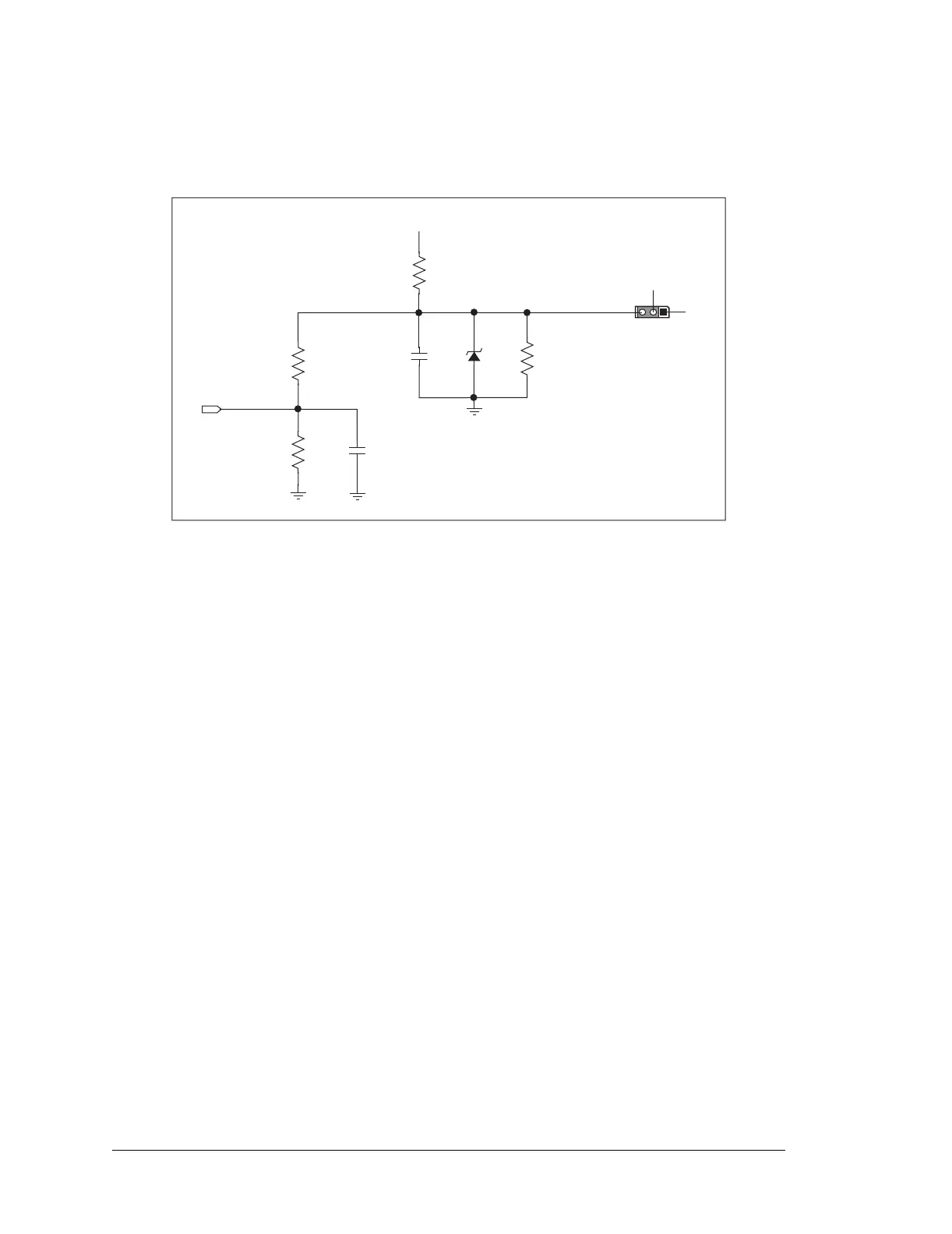
Figure 18 shows the analog voltage reference circuit.
Figure 18. Analog Reference Voltages
This circuit generates the 4.096 V reference voltage, which is used by the A/D converter
and optionally by the two D/A converters. This sets the operating range of the A/D con-
verter and the D/A converters (0–4.096 V). To use the full accuracy of the A/D converter
and the D/A converters, this voltage must be accurate to the same degree.
Under normal operation, the 453 Ω resistor is not installed. The reference zener diode in
combination with the 100 Ω resistor form a shunt regulator. The 4.096 V reference voltage
then feeds the A/D converter, the D/A converters, and the voltage divider composed of the
10 kΩ and the 14 kΩ resistors. The voltage divider generates a second reference voltage of
1.707 V to feed the four op-amps for the buffered A/D converter inputs.
The reference voltage can be ratiometric rather than absolute. This is done by removing
the zener diode and installing the 453 Ω resistor. With this arrangement, the reference
voltages follow changes in the power supply voltages Vcc and V+, which is a filtered ver-
sion of Vcc. This type of measurement circuit is preferred by some customers whose sen-
sors are powered from the Vcc supply and hence the outputs track Vcc.
A jumper on header JP3 allows the D/A converters to be powered either from the 4.096 V
reference (factory default) or from the analog supply +V. The D/A converters use their
power source also as the reference input, so normally powering the D/A converters from
the more accurate 4.096 V reference is best. However, should a customer desire more
dynamic range (0–5 V rather than 0–4.096 V), the jumper across JP3 can be set to power
the D/A converters from +V. When powered from the +V supply, the outputs of the D/A
converters will always be ratiometric, independent of whether the zener diode is installed.
10 kW
1.707_VREF
14 kW
100 nF
100 nF
100 W
+V
453 W
4.096_VREF
1
3
2
JP3
DAC_PWR
+ V
4.096 V
ref diode