sider
Z12
as
a divide-by-12 counter instead
of
a
divide
by
13 counter!
If
15.840 kHz
is
applied
to
Z12,
pin 14, then the
output
at pin
11
will
be
1.32 kHz.
The
next
divider
is
part
of
Z65. On Sheet 2,
follow
pin
11
of
Z12
up
to
Z65,
pin 14. The
output
is
at pin 12.
Follow
it
back down
to
Z32,
pin 14. This
part
of
Z65
divides the 1.32 kHz
input
by
two:
therefore, the frequency at pin 14
of
Z32
will
be
660.0 Hz.
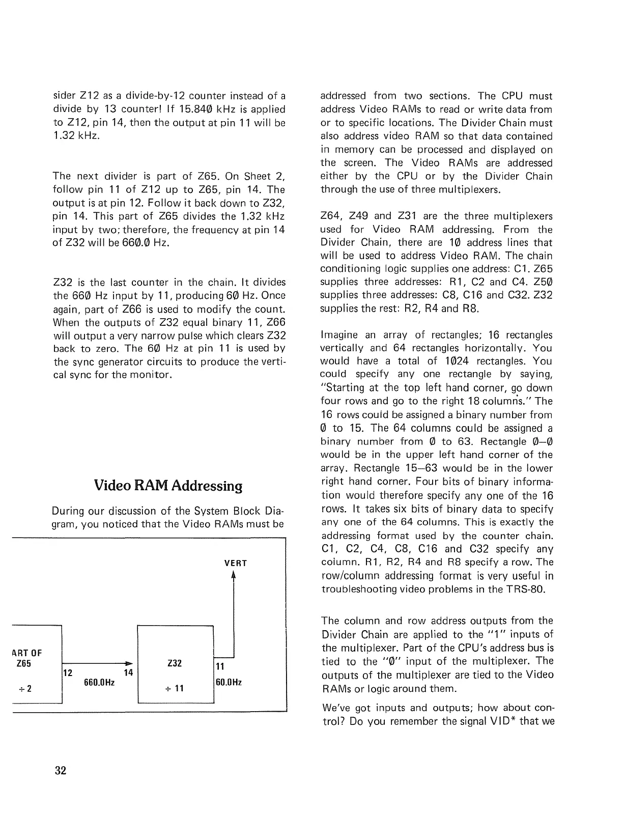
Z32
is
the last counter in the chain.
It
divides
the
660
Hz
input
by
11, producing
60
Hz. Once
again,
part
of
Z66
is
used
to
modify
the count.
When the
outputs
of
Z32
equal binary 11,
Z66
will
output
a very
narrow
pulse which clears Z32
back
to
zero. The
60
Hz at pin
11
is
used
by
the sync generator circuits
to
produce the verti-
cal
sync
for
the
monitor.
Video RAM Addressing
During
our
discussion
of
the System Block Dia-
gram, you noticed
that
the Video RAMs must
be
VERT
+
addressed
from
two
sections. The
CPU
must
address Video RAMs
to
read
or
write
data
from
or
to
specific locations. The Divider Chain must
also address video RAM
so
that
data contained
in memory
can
be
processed and displayed on
the
screen. The Video RAMs
are
addressed
either
by
the
CPU
or
by
the Divider Chain
through the
use
of
three multiplexers.
Z64,
Z49
and Z31
are
the three multiplexers
used
for
Video RAM addressing. From the
Divider Chain, there
are
10 address lines
that
will
be
used
to
address Video RAM. The chain
conditioning
logic supplies one address: C1.
Z65
supplies three addresses: R1,
C2
and C4.
Z50
supplies three addresses: C8, C16 and C32.
Z32
supplies the rest: R2, R4 and R8.
Imagine
an
array
of
rectangles; 16 rectangles
vertically and
64
rectangles
horizontally.
You
would
have
a
total
of
1024 rectangles. You
could specify
anyone
rectangle by saying,
"Starting
at the
top
left
hand corner,
go
down
four
rows and
go
to
the
right
18
columns."
The
16 rows could
be
assigned
a binary number
from
o
to
15. The
64
columns could
be
assigned
a
binary number
from
0
to
63. Rectangle
0-0
would
be
in the upper
left
hand corner
of
the
array. Rectangle
15-63
would
be
in the lower
right
hand corner.
Four
bits
of
binary informa-
tion
wou
Id
therefore specify
anyone
of
the 16
rows.
It
takes six bits
of
binary data
to
specify
anyone
of
the
64
columns. This
is
exactly the
addressing
format
used
by
the counter chain.
Cl,
C2, C4, C8, C16 and C32 specify any
column. R1, R2,
R4
and
R8
specify a row. The
row/column
addressing
format
is
very useful in
troubleshooting video problems in the TRS-80.
ART
OF
Z65
+2
12 14
660.0Hz
32
Z32
+
11
>---
11
60.0Hz
The column and
row
address
outputs
from
the
Divider Chain are applied
to
the
"1"
inputs
of
the multiplexer. Part
of
the CPU's address bus
is
tied
to
the
"0"
input
of
the multiplexer. The
outputs
of
the
multiplexer
are tied
to
the Video
RAMs
or
logic around them.
We've got inputs and
outputs;
how
about con-
trol? Do you remember the signal
VID*
that
we
 Loading...