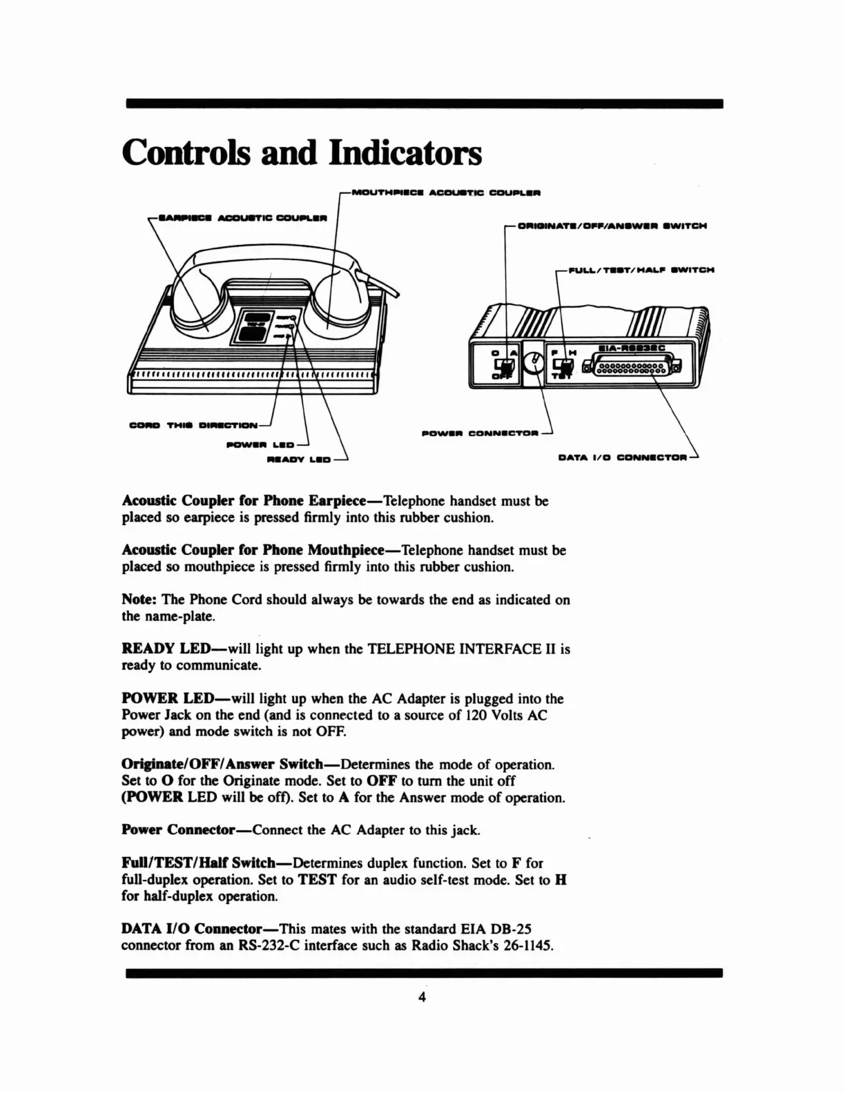
Controls and Indicators
OATA
I/O
CO~CTO.
....
I".
~ICCDI""'
••
'"""'""""""1/'''1/''
"1/ "'''1/1/'
Acoustic Coupler for Phone
Earpiece-Telephone
handset must
be
placed so earpiece is pressed firmly into this rubber cushion.
Acoustic
Coupler
for Phone
Mouthpiece-Telephone
handset must be
placed so mouthpiece
is
pressed firmly into this rubber cushion.
Note: The Phone Cord should always be towards the end
as
indicated on
the name-plate.
READY
LED-will
light up when the TELEPHONE INTERFACE II
is
ready to communicate.
POWER
LED-will
light up when the
AC
Adapter is plugged into the
Power Jack on the end (and
is
connected to a source of
120
Volts
AC
power) and mode switch is not
OFF.
Originate/OFF/
Answer
Switch-Determines
the mode
of
operation.
Set to
0 for the Originate mode. Set to
OFF
to
tum the unit off
(POWER
LED will
be
ofO.
Set to A for the Answer mode
of
operation.
Power
Connector-Connect
the
AC
Adapter
to
this jack.
Full/TEST/Half
Switch-Determines
duplex function. Set
to
F for
full-duplex operation. Set to
TEST
for an audio self-test mode. Set
to
H
for half-duplex operation.
DATA
I/O
Connector-This
mates with the standard EIA DB-25
connector from an RS-232-C interface such
as
Radio Shack's
26-1145.
4
 Loading...