RadioLink Electronic Limited
www.radiolink.com
control. That is, Master-Steering, Slave-Throttle. Enter PMIX02 in the menu to modify.
* Percentage value varies the turning angle;
”-”means Master and Slave move to different directions at the same time
* For more detailed information on function setting please refer to the product user manual on
www.radiolink.com .
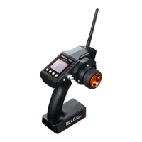
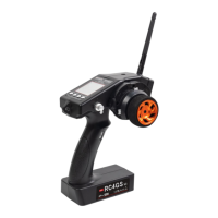
Size: 213 *117 * 115.5mm(6.39”*3.51”*3.46”)
Weight: 330g(11.6oz)
Channel: 4CH
Antenna Length: 106mm(4.17")
Control Range: 400m(437yd)
Operating Current: 80-120mA
Operating Voltage: 4.8-15V
(6pcs of AA battery or 2S-4S LiPo battery)
RF Power: <20dbm
Frequency: 2.4Ghz ISM Band(2400.0MHz--2483.5MHz)
Modulation Mode: GFSK
Channel resolution: 4096, the regular jitter is 0.5us
Spread Spectrum: FHSS
67 Channels Pseudo Random Frequency Sequence Hopping
LCD Screen: 128*64 Resolution, LCD Back Light
Low Voltage Alarm: Yes (can be customized on 2S-4S battery)
Adaptable Models: Fishing boats, Robots,Vehicles(Crawlers/Tanks/Truck)
Compatible Receiver: R6FG, R6F, R8EF, R8F, R7FG, R4FGM,R4F
Battery Tray Dimension: 89*59*18mm (3.5”*2.32”*0.71)
Model Memory: 10
For more after-sales service:
Please start from www.radiolink.com to download the electronic detailed manual.
Or send mail to: after_service@radiolink.com.cn /after_service1@radiolink.com.cn
Thank you again for choosing our product.
Size: 35*20*13mm (1.05"*0.6"*0.39")
Weight: 6g(0.21oz)
Channel: 6CH
Antenna Length: 172mm(6.77")
Operating Current: 30mA
Operating Voltage: 4.8-10V
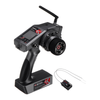
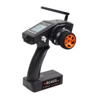
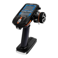
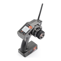
RC4GS V2 Specification R6FG Specification
 Loading...