D2212 Installation Manual
Page 3
© 1996 Radionics
74-07361-000-C 11/11/96
Introduction
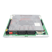
D2212 Control/Communicator
The Radionics D2212 Control/Communicator is shipped pre-
assembled from the factory. You should receive the following
parts with your D2212 panel.
Panel Assembly
• D2212 Panel
• D2203 Enclosure
• D1640 Transformer
•
Technogram: Smoke Detectors Compatible with the
D2212
(73-07358-000)
• Release Notes (74-07460-000)
Hardware Pack
• One 2k Ω end-of-line resistor for Point 1 (
15-03130-010)
• Six 1k Ω end-of-line resistors for Points 2 to 6 (there is
one extra 1k Ω resistor)
(30-01098-102)
• Four #6 sheet metal screws
• Five plastic stand-offs for mounting board to enclosure
Ordered Separately
Literature Pack
•
D2212 Installation Manual
(74-07361-000)
•
D2212 Program Entry Guide
(74-07386-000)
•
D2212 Program Record Sheet
(74-07387-000)
D202A LED Keypad
Each D202A includes the following.
•
D202A Keypad
•
Installation Sheet
(74-07118-000)
•
User's Cards
(71-07090-000)
•
Security System User's Guide
(71-07117-000)
•
Getting Started w/Your Security System
(71-07372-000)
•
Three-wire cable assembly
(15-07032-000)
D220A LED Keypad
Each D220A includes the following.
•
D220A Keypad
•
Installation Sheet
(74-07511-000)
•
User's Reference Card
(71-04532-011)
•
Security System User's Guide
(71-07374-000)
•
Getting Started w/Your Security System
(71-07372-000)
•
Three-wire data cable assembly
(15-07032-000)
D222 Text Keypad with Point Expansion
Each D222 includes the following.
•
D222 Text Keypad with Point Expansion (4 points)
•
Installation Sheet
(74-07362-000)
•
User's Reference Card
(71-04523-010)
•
Security System User's Guide
(71-07374-000)
•
Getting Started w/Your Security System
(71-07372-000)
•
Three-wire data cable assembly
(15-07032-000)
•
Six-wire point cable assembly
(15-07251-000)
• Four 1k Ω end-of-line resistors (30-01098-102)
Table of Contents
Introduction ........................................................................ 3
D2212 Control/Communicator ..................................... 3
Ordered Separately...................................................... 3
Enclosure Options........................................................ 4
Listings and Approvals ................................................. 4
Getting Started ................................................................... 4
Mount the Enclosure and Board .................................. 4
Run the Premises Wiring ............................................. 4
Connect Earth Ground ................................................. 5
Transformer ................................................................. 5
Battery.......................................................................... 5
Charge the Battery as You Work ...................................... 5
Lock the Standby Switch.............................................. 5
Install Detection Devices,.................................................. 6
Keypads, and Bells ............................................................ 6
No Connections to the Panel Yet ................................. 6
Number of Sensors ...................................................... 6
Continue Connections to the Panel ................................. 6
Power Down First ......................................................... 6
Alarm Output................................................................ 6
Keypads ....................................................................... 6
Auxiliary Power ............................................................ 7
External Relays ............................................................ 7
Connect the Points ............................................................ 7
On-Board Points .......................................................... 7
Point 1 .......................................................................... 7
Points 2 to 6 ................................................................. 8
Points 7 and 8 .............................................................. 8
Point Expanders, Wired or RF ..................................... 8
Make the Telephone Connections .................................... 9
Power Up ..................................................................... 9
Program the Panel ....................................................... 9
Unlock the Standby Switch .......................................... 9
Fill out the Point Chart ............................................... 10
Test the System ......................................................... 10
Detailed Panel Description.............................................. 10
Primary (AC) Power Circuit ........................................ 10
Secondary (DC) Power .............................................. 10
Power Outputs ........................................................... 11
Telephone .................................................................. 11
Points ......................................................................... 12
Keyswitch ................................................................... 12
Installation Guide for UL Applications........................... 13
Introduction ................................................................ 13
Optional Compatible Equipment ................................ 13
System Chart .................................................................... 14
Standby Battery Requirements .................................. 14
System Wiring Diagram, Issue A .................................... 14
Current Rating Chart for Standby Battery Calculations 15
Specifications................................................................... 16
D2212 Terminal Quick Reference ................................... 16
www.PDF-Zoo.com