R
eactor-Ready - Lab Reactor
8. Set-Up & Operation - Continued
8
.5. Locating the support braces
8.5.1 The Reactor-Ready core includes four Safety Stop Collars that limit the downward
movement of the Stirrer Support I-Brace and Vessel Support Clamp. Two collars are
positioned and secured (one on each rod) under each of the two support braces.
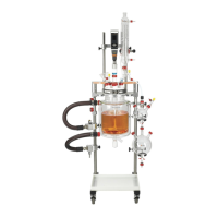
8.5.2 Attach the Vessel Support Clamp to the framework by first sliding two Safety Stop
Collars onto the Side Support Rods (one on each outer rod), sliding to the required position
and tightening the locking knobs to secure. Then slide the Vessel Support Clamp onto the
outer two Support Rods. Slide it down the rods until it is in the required position and tighten
the two outer locking knobs to secure. Adjust the Safety Stop Collars so that they are located
directly under the Support Brace, and re-tighten.
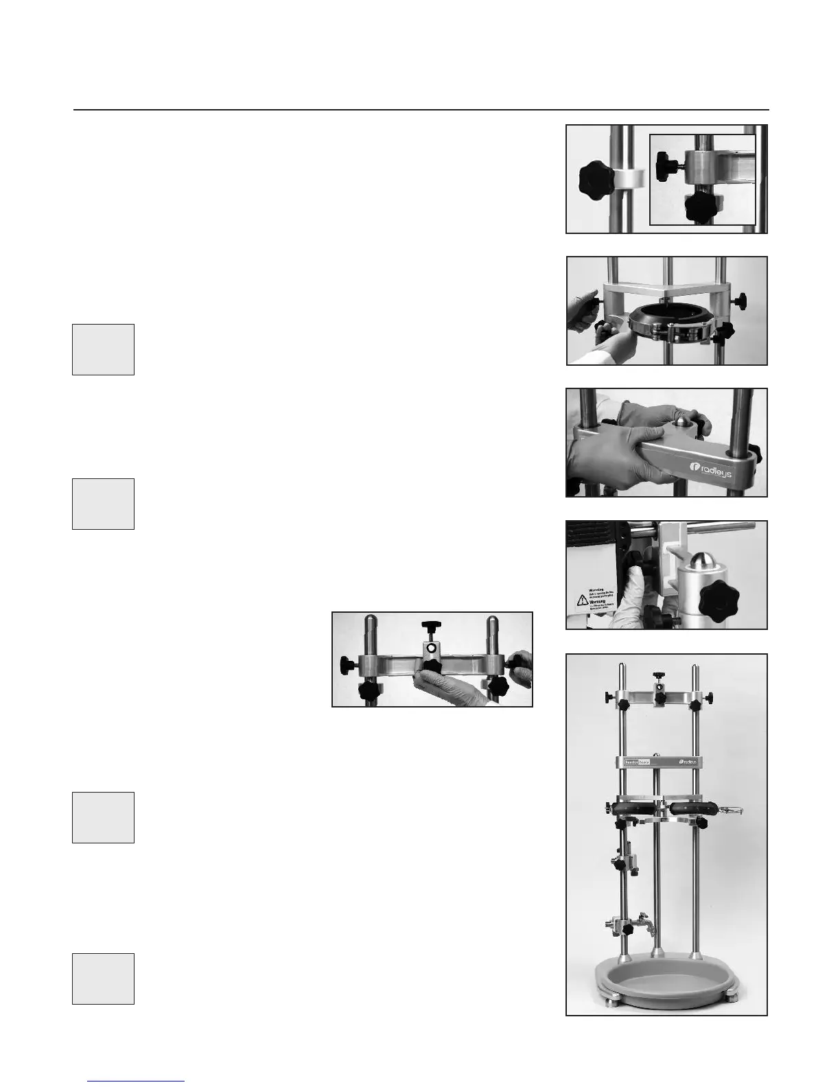
8.5.3 Attach the T-Beam Support Brace to the framework by sliding it onto firstly the two
outer Support Rods, then moving it down to locate onto the third shorter Central Rod. Once
the Brace is fully located on the Central Rod secure it by tightening the three locking knobs.
This Brace is solely to add stability and maintain alignment of the framework.
8.5.4 The Stirrer Support I-Brace is designed to support an overhead stirrer and features
precision bore slide bearings enabling smooth height adjustment - offering maximum user
flexibility in configuring the system.
8.5.5 Attach the Stirrer Support I-Brace to the
framework by first sliding two Safety Stop Collars
onto the Side Support Rods (one to each rod),
sliding to the required position and tightening the
locking knobs to secure. Then slide the Stirrer
Support I-Brace onto the two outer Side Rods,
before moving it down to the required position
and securing with the two locking knobs. Ensure that the Brace is orientated such that the
two knobs on the central sliding boss are pointing upwards and forwards. Adjust the Safety
Stop Collars so that they are located directly under the Stirrer Support I-Brace, and re-
tighten.
8.6 Preparing the reaction vessel
8.6.1 Reactor-Ready is capable of supporting a range of dedicated reaction vessels ranging
in size from 250ml to 5000ml in either single jacket or vacuum jacket format.
Important Note - In some circumstances it may be preferable to locate
the Vessel Support Clamp between the Inlet and Outlet Manifolds, rather than
above them, to give optimal spatial alignment of system components.
Important, Important,
Important, Important,
Important, Important,
Important, Important,
Important, Important,
I
mportant, Important,
Important Note - Moving parts should be kept clean and free from any
obstructions or surface contamination. Parts relying on sliding motion may
benefit from regular application of a thin surface coating of lubricating oil.
Important, Important,
Important, Important,
Important, Important,
Important, Important,
Important, Important,
Important, Important,
Page 10
Important Note - All 3 poles must be engaged with the T-Beam Support
Brace to ensure proper alignment and stability.
Important, Important,
Important, Important,
Important, Important,
I
mportant, Important,
I
mportant, Important,
I
mportant, Important,
8.5.1
8.5.3
8.5.4
8.5.5
8.5.2
Important Note - Reactor-Ready clamp assembly is NOT designed to
accept reactors from other manufacturers. The vessel neck, flange and lid
geometry are specifically engineered to ensure a safe and leaktight seal.
Important, Important,
Important, Important,
Important, Important,
Important, Important,
Important, Important,
Important, Important,
 Loading...