SECTION 2 - GUIDE RAILS AND CROSS BRACES.
Page 2-7
Rev 1A – Oct. 2003
2.8
Tighten all bolts on the guide rails, cross braces, and counter weight guide angles starting from the bottom to top in the
following sequence:
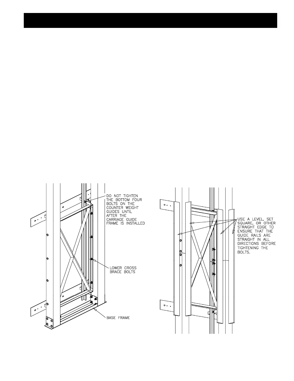
a) Tighten the base frame first followed by the lower cross brace (FIG. 8) Ensure cross brace is flush with back of rail.
(do not tighten the wall mounting brackets or the counter weight guides at this time).
b) Tighten the guide rail connector sections and mid-cross brace ensuring that the rails make a straight line where they
connect. Tighten to about 80 ft-lbs, do NOT over tighten. IMPORTANT: Using a 4’ level or a set square ensure that
the guide rails are in line and square in all directions (FIG. 9) (do not tighten the wall mounting brackets or the counter
weight guides at this time).
c) Tighten the bolts on the upper cross brace and motor base frame.
d) Tighten the counterweight guide connecting angles (Figure 6) Ensure counterweight guide angles edges are lined
up and are tight together. Grind connection smooth if necessary.
e) Move guide frame assembly back to supporting wall and anchor the wall mounting brackets to the supporting wall.
Center guide rails in shaft by measuring from 4” x 4” rail to shaft walls adjacent to the support wall.
f) Tighten all of the counter weight guide angle bolts except for the ones on the lower cross brace (FIG. 8).
Figure 8. Tightening the base frame and lower cross
brace, looking from in front of the guide rails.
Figure 9. checking that the guide rails are straight
and square, looking from in front of the guide rails.