SECTION 2 - GUIDE RAILS AND CROSS BRACES.
Page 2-6
Rev 1A – Oct. 2003
2.6
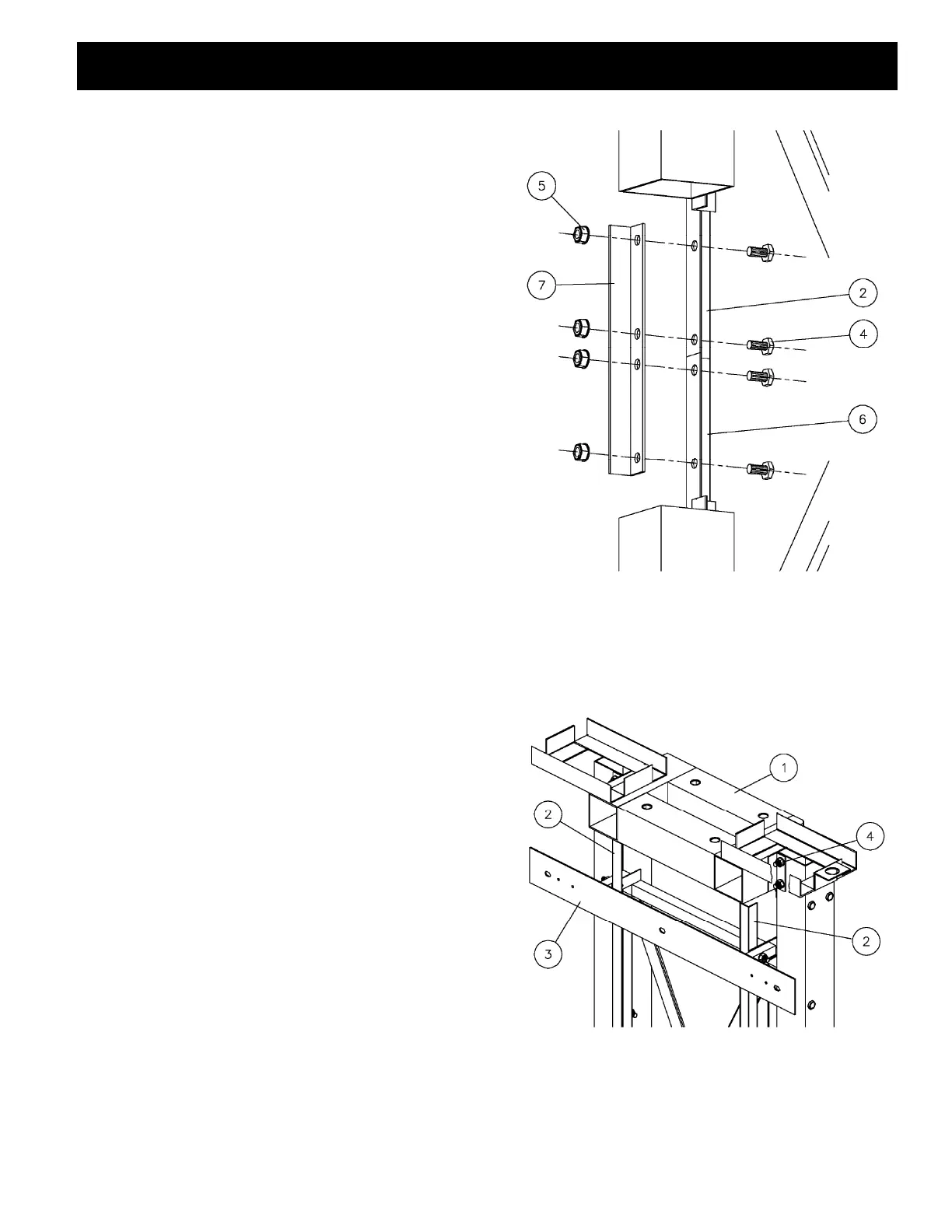
Install counter weight guide connecting angle (FIG. 6).
Leave all bolts loose.
2.7
Install battery base frame (FIG. 7).
Figure 6. Installation detail of the counter weight
guide connecting angle. Looking from in front of the
guide rails, with part of the guide rail and cross
brace cut away for clarity.
NOTE:
Refer to shop drawings for each job for details of this
item.
MATERIAL LIST PART #
1 Gear Drive base frame FFCUG017
2. Upper counter weight guides FFBUG012
3. Wall mounting bracket FFBUG008
4. 7/16 N.C. x 1 bolt PGAGF006
5. 7/16 nylon lock nut PGAGF030
6. Lower counter weight guide *NOTE
7. Counter weight guide connecting
angle
FFBUG016
Figure 7. Gear Drive base frame and counter weight
guides installation, looking from behind the guide
rails.