SECTION 3 - MOTORS AND RUNNING GEAR
Page 3-2
Rev 1B – May 2013
3.2
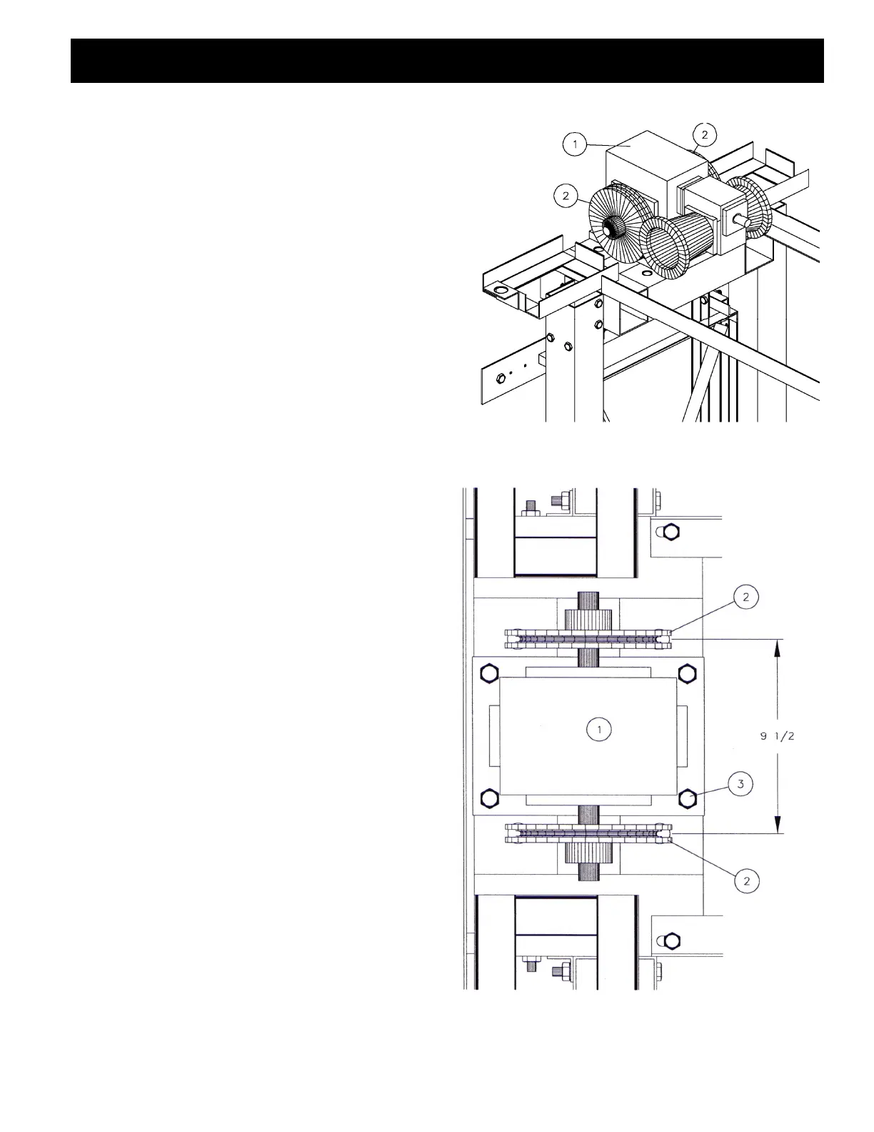
Mount the gear reducer on to the mounting base at the top
of the guide rail assembly (FIG. 2). The sheaves should
have been installed at the shop, and should be secured
with a roll pin through the boss.
3.3
Ensure that the sheaves are 9 1/2” centre to centre
(FIG. 3).
Figure 2. Installation of gear reducer assembly.
Looking from in front of the guide rails.
NOTE:
MATERIAL LIST PART #
1. Gear reducer assembly
2. Traction sheave MMBUG080
3. 7/16 N.C. x 5 1/2 bolt PGAGF015
Figure 3. Sheave spacing.