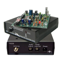
FM100B • 29
38D. Install R45, a 121K ohm 1% resistor (brown-red-brown-orange-brown).
39D. Install R44, a 121K ohm 1% resistor (brown-red-brown-orange-brown).
40D. Install R60, a 61.9K ohm 1% resistor (blue-brown-white-red-brown)
41D. Install C57, a 68 pF 5% ceramic capacitor (marked 68).
42D. Install C47, another 68 pF 5% ceramic capacitor (marked 68).
43D. Install C54, a 680 pF 5% ceramic capacitor (marked 681).
44D. Install C60, a 0.0022 uF 5% ceramic capacitor (marked 222).
45D. Install C56, an 82 pF 5% ceramic capacitor (marked 82).
46D. Install C61, a 22 pF 5% ceramic capacitor (marked 22).
47D. Install C62, a 180 pF 5% ceramic capacitor (marked 181).
48D. Install C55, a 56 pF 5% ceramic capacitor (marked 56).
49D. Install U4, another LF347N opamp. This opamp and the surrounding
parts handles the Right channel audio filtering. Check all 14 pins before
soldering.
50D. Install C52, a 10 uF electrolytic capacitor. Check orientation before
soldering as these are polarity sensitive!
51D. Install C48, another 10 uF electrolytic capacitor.
52D. Install C72, yet another 10 uF electrolytic capacitor.
53D. Install C53, one more 10 uF electrolytic capacitor.
Check your work up to this point to be sure you didn’t make a mistake. It is
much easier to check your work in small manageable groups than all at once.
Again check for solder bridges and cold solder joints. Especially check around
the pins of the ICs for solder bridges since it is a common occurrence.