FM100B • 43
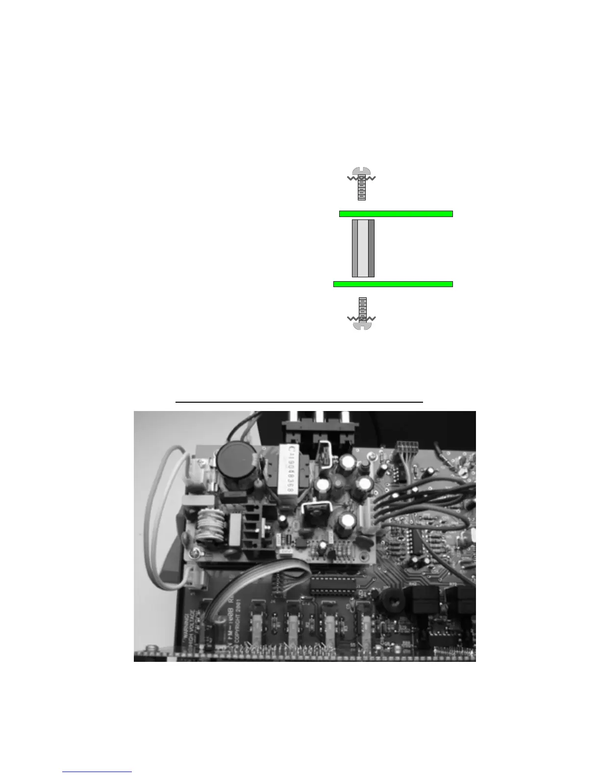
4J. Locate the 4 #4-40x5/8” standoffs and 8 of the #4-40x1/4” screws (with
captured star washers).
5J. Install the 4 standoffs in the holes as shown below on the main board.
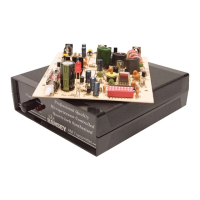
6J. Once installed, place the power supply on the standoffs and use the
remaining 4 screws to mount the power supply module. Note the
orientation of the jacks on the power supply. It should be the same as
shown below in reference to the main board.
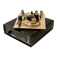
7J. Use the pre-made 4-pin to 4-pin
Molex wire jumper to connect between
the power output on PS1 to the
connector on the main board (J3). Do not
twist the cable, the wires should be a one
to one match. The locking headers
should snap them into place.
8J. Use the pre-made 3-pin to 3-pin
Molex wire jumper (note that only two
wires are used) to go between J1 and the
AC IN jack of the power supply.
Orientation is not as critical here but use the locking headers as a guide.
#4-40x1/4" Screw
#4-40 5/8" Standoff
Main Board
#4-40x1/4" Screw
Power Supply
PS1 POWER SUPPLY WIRING CLOSE-UP