Basic Measurement Examples
R&S
®
ESR
104Getting Started 1316.3749.02 ─ 09
frequency). The resolution bandwidth and the frequency offset must be selected
in such a manner that the instantaneous frequency is located in the linear part of
the filter edge. As a result, the frequency variation of the FM-modulated signal is
transformed into an amplitude variation that can be displayed on screen in zero
span.
Displaying the AF of an FM-Modulated Carrier
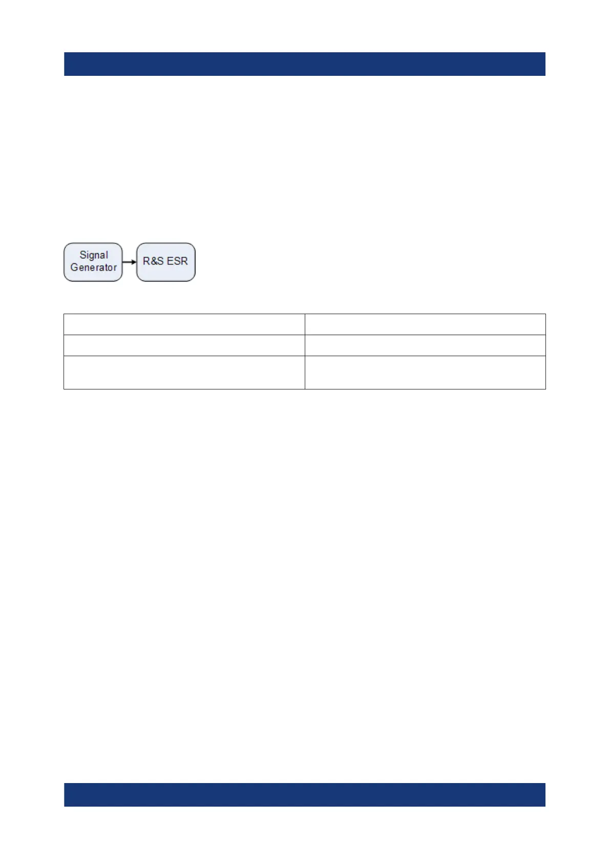
Test setup
Table 7-8: Signal generator settings (e.g. R&S SMU)
Frequency 128 MHz
Level -20 dBm
Modulation FM 0 kHz deviation (i.e. FM modulation is
deactivated), 1 kHz AF
1. Set the signal analyzer to the default state by pressing the [PRESET] key.
The R&S ESR is set to its default state.
2. Select "Spectrum" mode.
3. Set the center frequency to 127.50 MHz and the span to 300 kHz.
a) Press the [FREQ] key and enter 127.50 MHz.
b) Press the [SPAN] key and enter 300 kHz.
4. Set the resolution bandwidth to 300 kHz.
a) Press the [BW] key.
b) Press the "Res BW Manual" softkey and enter 300 kHz.
c) Press the "Video BW Manual" softkey and enter 30 kHz.
5. Set the display range to 20 dB and shift the filter trace to the center of the
screen.
a) Press the [AMPT] key.
b) Press the "Range" softkey
c) Press the "Range Log Manual" softkey and enter 20 dB.
d) Press the "Up↑" softkey.
e) Press the "More" softkey.
f) Switch the "Grid" softkey to "Rel".
g) Press the "Up↑" softkey.
Measurements in Zero Span

 Loading...

