Instrument Tour
R&S
®
ESR
17Getting Started 1316.3749.02 ─ 09
4 Instrument Tour
On the instrument tour, you can learn about the different control elements and
connectors on the front and back panel of the R&S ESR.
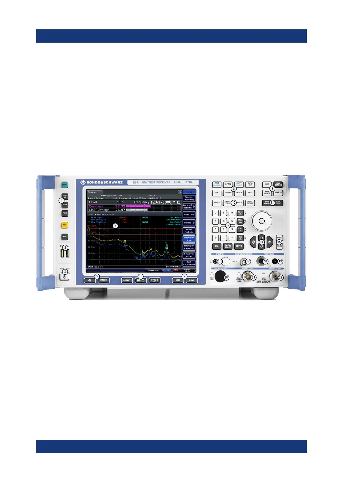
4.1 The Front Panel
The front panel of the R&S ESR is shown in Figure 4-1. Each element (function
keys and connectors) is described in more detail in the subsequent sections.
Figure 4-1: Front panel of the R&S
ESR
1 = Function keys
2 = USB interface
3 = Power button
4 = Display
5 = Access to operating system and online keyboard
6 = Display options
7 = Navigation options for menus
8 = Measurement configuration
9 = Marker functions
10 = Measurement control
11 = Measurement start
12 = Data entry keys
13 = Rotary knob
14 = Navigation keys
15 = Undo / redo function
The Front Panel

 Loading...

