Instrument Tour
R&S
®
ESR
24Getting Started 1316.3749.02 ─ 09
The output of the tracking generator is connected to the DUT via a cable equip-
ped with a male N connector. The female connector is available only with the
tracking generator option (R&S FSV-B9).
Sensitive DUTs concerning matching
For DUTs with sensitive RF characteristics with regard to matching (VSWR)
at the input, insert a 10 dB attenuator between the DUT and the tracking
generator.
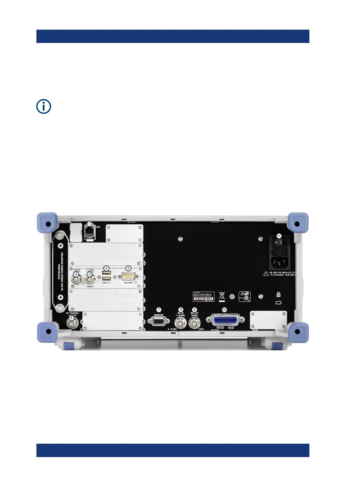
4.2 Rear Panel View
The rear panel of the R&S ESR is shown in Figure 4-3. Each element is descri-
bed in more detail in the subsequent sections.
Figure 4-3: R&S
ESR rear panel
1 = LAN interface
2 = Trigger output
3 = IF / Video connector
4 = USB interface
5 = AUX port
6 = External trigger / gate input
7 = VGA interface
8 = Reference in
Rear Panel View

 Loading...

