Instrument Tour
R&S
®
ESR
27Getting Started 1316.3749.02 ─ 09
You can select between IF and video output with the functionality provided in the
"In-/Output" menu ([INPUT/OUTPUT] key).
4.2.10 USB
The rear panel provides two female USB connectors to connect devices like an
external keyboard or mouse. You can also connect a memory stick to save and
restore instrument settings and measurement data.
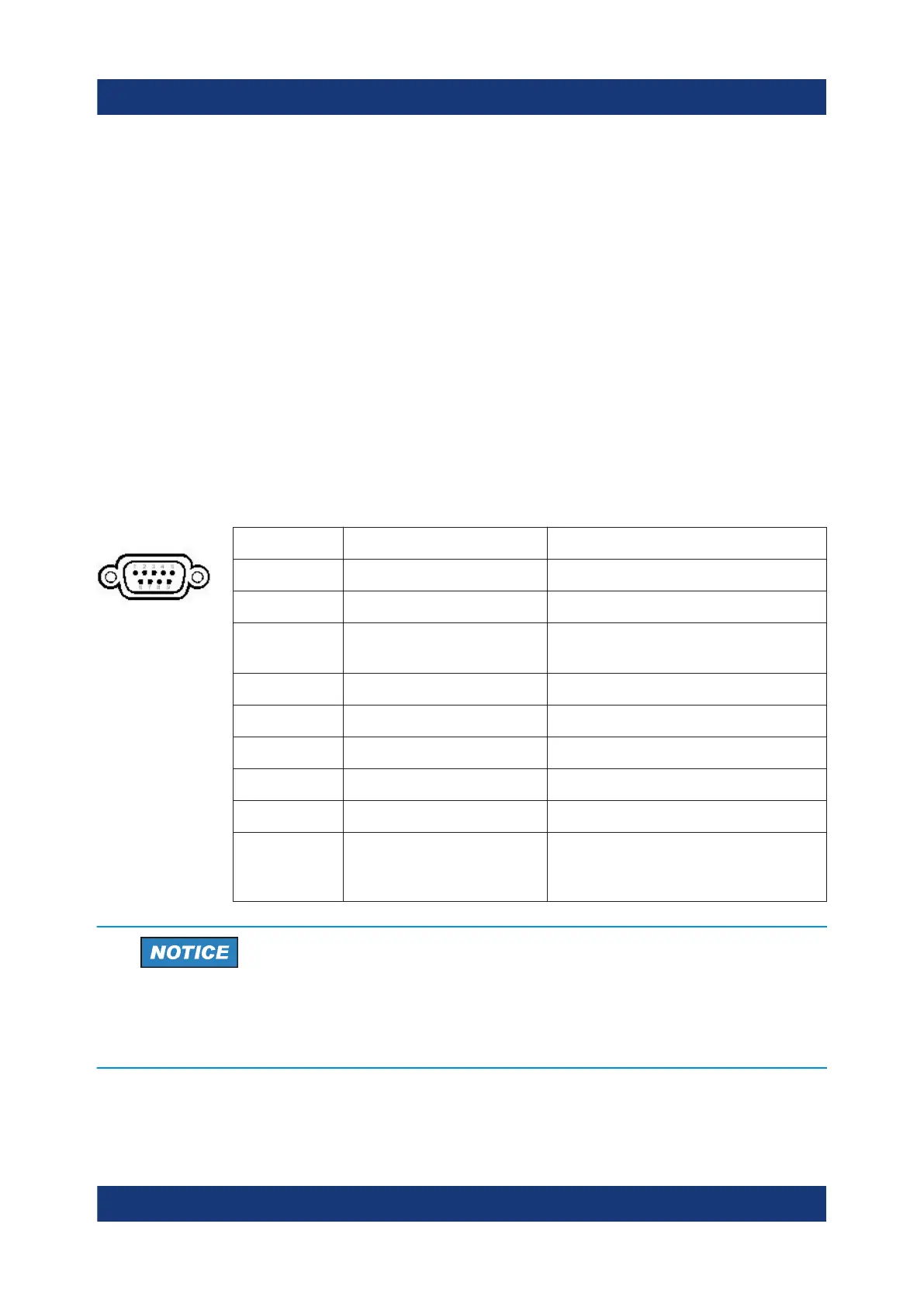
4.2.11 AUX Port
The 9 pole SUB-D male connector provides control signals for controlling external
devices. The voltage levels are of the TTL type (5 V).
Pin Signal Description
1 +5 V / max. 250 mA Supply voltage for external circuits
2 I/O Control Phase N
3 I/O Controls the 150 kHz highpass fil-
ter
4 I/O Controls Phase L3
5 I/O not used
6 I/O Controls Phase L1
7 I/O Controls Phase L2
8 GND Ground
9 READY FOR TRIGGER Signal indicating that the instru-
ment is ready to receive a trigger
signal (Low active = 0 V)
Short-circuit hazard
Always observe the designated pin assignment. A short-circuit can damage
the port.
Rear Panel View

 Loading...

