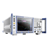
Instrument Tour
R&S
®
ESR
23Getting Started 1316.3749.02 ─ 09
4.1.5 RF Input 50Ω
The R&S ESR provides two RF inputs for connection of a device under test
(DUT) to the R&S ESR. The DUT is connected to the RF Input via cable and an
approriate connector (for example a male N connector).
The first RF Input supports a frequency range from 9 kHz to f
max
and an attenua-
tion range from 0 dB to 75 dB. The second RF Input supports a frequency range
from 9 kHz to 1 GHz and an attenuation range from 10 dB to 75 dB. Attenuation
levels smaller than 10 dB are not possible at RF Input 2.
With option R&S ESR-B29, the minimum frequency is extended to 10 Hz at both
RF inputs.
4.1.6 Probe Power
The R&S ESR provides two connectors to supply accessories like transducers or
probes with power.
The probe power connector with five pins supports supply voltages of ±10 V and
ground. The maximum permissible current is 200 mA. This probe power connec-
tor is suitable, for example, for transducers from Rohde & Schwarz.
The probe power connector with three pins supports supply voltages from +15 V
to -12.6 V and ground. The maximum permissible current is 150 mA. This probe
power connector is suitable, for example, for high-impedance probes from Agi-
lent.
4.1.7 AF Output
Headphones equipped with a miniature jack plug can be connected to the AF out-
put female connector. The internal impedance is 10 Ω. The output voltage can be
set by using the volume control to the right of the female connector. If a plug is
connected, the internal loudspeaker is automatically switched off.
See also "Connecting headphones" on page 9.
4.1.8 Tracking Generator Output (Optional)
The R&S ESR is equipped with an optional tracking generator and therefore pro-
vides a tracking generator output connector.
The Front Panel

 Loading...