Basic Operations
R&S
®
ESR
49Getting Started 1316.3749.02 ─ 09
results even though this is not immediately apparent from the display of the mea-
sured values. This information is displayed in gray font and only when applicable
for the current measurement, as opposed to the common hardware settings that
are always displayed.
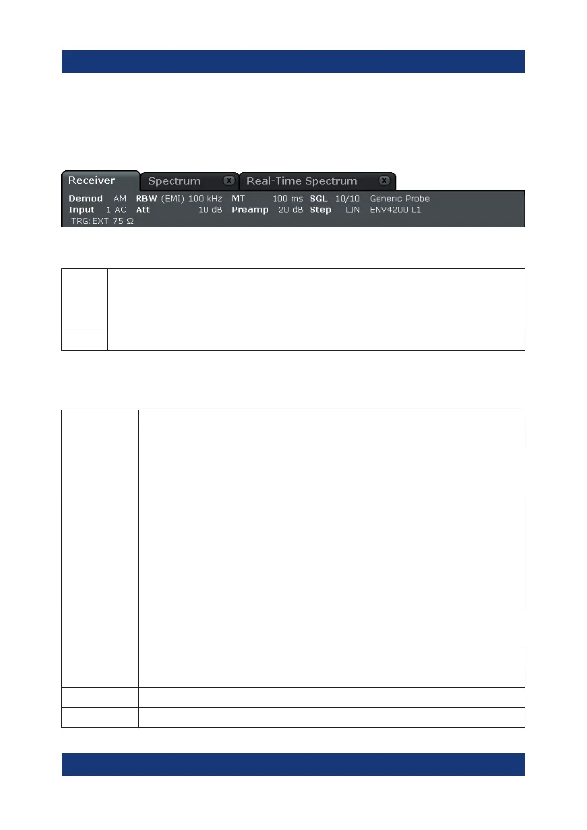
In Receiver mode, the R&S ESR shows the following information.
TRG Trigger source
(for details see trigger settings in the "TRIG" menu in the Operating manual)
●
EXT: External
●
VID: Video
75 Ω The input impedance of the instrument is set to 75 Ω.
In Spectrum mode, the following types of information may be displayed, if applica-
ble.
Label Description
SGL The sweep is set to single sweep mode.
Sweep Count The current signal count for measurement tasks that involve a specific number
of subsequent sweeps
(see "Sweep Count" setting in "Sweep" menu in the Operating manual)
TRG Trigger source
(for details see trigger settings in the "TRIG" menu in the Operating manual)
●
EXT: External
●
VID: Video
●
RFP: RF power
●
IFP: IF power
●
TIM: Time
●
SQL: Squelch
6dB/RRC/CH
N
Filter type for sweep bandwidth
(see BW menu in the Operating manual)
PA The preamplifier is activated.
GAT The frequency sweep is controlled via the [EXT TRIG/GATE IN] connector.
TDF A transducer factor is activated.
75 Ω The input impedance of the instrument is set to 75 Ω.
Information in the Diagram Area
 Loading...