Operating Concepts
R&S
®
NRPxxS(N)
39User Manual 1177.5079.02 ─ 10
Setup
NRP
3-Path Diode Power Sensor
MHz to GHz, 100 pW to 200 mW (−70 dBm to +23 dBm)
SMART SENSOR TECHNOLOGY
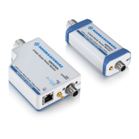
Figure 5-5: Setup with an R&S NRP2 base unit
1 = Signal source
2 = R&S NRPxxS(N) power sensor
3 = Host interface connector
4 = R&S NRP‑ZK6 cable
5 = Sensor input connector of the R&S NRP2
6 = R&S NRP2 base unit
Incorrectly connecting/disconnecting the R&S NRPxxS(N) power sensors can damage
the power sensors or lead to erroneous results.
Ensure that you connect/disconnect your power sensor as described in Chapter 3,
"Preparing for Use", on page 11.
Starting a measurement
1. Connect the cables as shown in Figure 5-5:
a) Connect the R&S NRP‑ZK6 cable to the host interface connector of the sensor.
b) Connect the R&S NRP‑ZK6 cable to a sensor input connector of the R&S
NRP2.
c) Connect the [RF] connector of the power sensor to the signal source.
2. Preset the R&S NRP2.
a) Press the [(PRE)SET] hardkey.
The "File" menu appears.
b) Press the [(PRE)SET] hardkey again or press the "Preset" softkey.
All parameters are set to their defaults, even when in inactive operating modes.
3. Execute zeroing:
Note: Turn off all measurement signals before zeroing. An active measurement
signal during zeroing causes an error.
a) Switch off the power of the signal source.
R&S NRP2
 Loading...

