Scanner tour
R&S
®
QPS Walk2000
16Getting Started 1179.5782.02 ─ 03
1
2
3 4 5 6 7
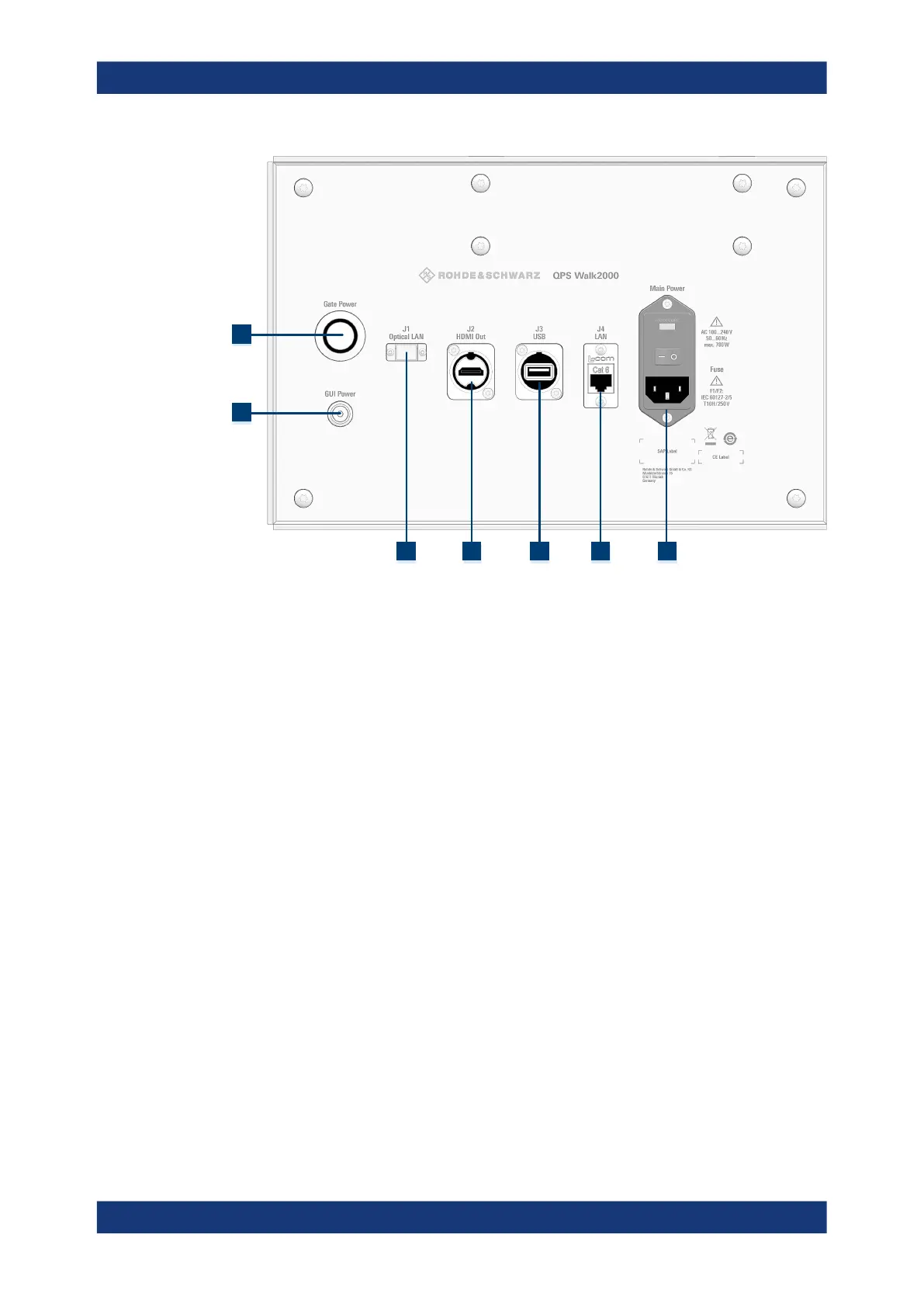
Figure 4-1: Gate controls and connectors
1 = Gate power button
2 = GUI power button
3 = Optical fiber connector (J1)
4 = HDMI connector (J2)
5 = USB port (J3)
6 = LAN port (J4)
7 = Main power switch and connector
For a comprehensive description of the connectors and controls of the server, refer to
its documentation available on the internet: www.dell.com
4.2 AC power supply
The AC power supply and the main power switch are located in a unit behind a protec-
tive cover on the side of the R&S QPS Walk2000.
The main power switch has the following states.
●
Position "I": The R&S QPS Walk2000 is supplied with power.
●
Position "O": The R&S QPS Walk2000 is disconnected from the power source.
For more information about taking the R&S QPS Walk2000 into operation, see Chap-
ter 5, "Preparing for use", on page 19.
For more information about replacing the fuse, see Chapter 6.3, "Replacing fuses",
on page 24.
AC power supply
 Loading...