34
Key
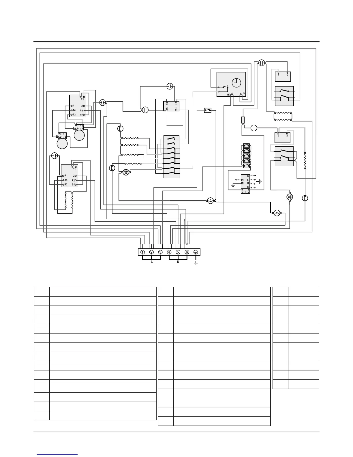
The connections shown in the circuit diagram are for single-phase. The ratings are for 230 V 50 Hz.
10. Circuit Diagram
Code Colour
b Blue
br Brown
bk Black
or Orange
r Red
v Violet
w White
y Yellow
g/y Green/yellow
gr Grey
ArtNo.081-0011 - 110DF - Circuit diagram - Excel
6
P6
5 P5
4
P4
7 P7
8 P8
2
P2
1 P1
3 P3
P038434
1.1kW
1.1kW
a
b
e
f
c
d
1
2
P095199
1
2
P2
P1
P095199
1
2
P2
P1
b
w
b
br
bk
bk
b
b
b
b
bk
w
b
y
y
br
br
y
y
v
r
br
br
b
r r
b
w
b
v
r
v
r
w
r
gr
w
y
b
b
br
br
or
w
y
b
b
r
b
b
b
br
w
b
gr
w
v
b
r
ry
y br
r b
w
b
b
or
bk
bk
bk
or
or
gr
bv
vbr
vbr
vbr
vbr
v
br
v
b
r
bk
bk
bk
b
r
bk
bk
r
v
br
bk
b
br
v
r
br
br
b
or
b
b
br
b b b
b
bb b
b
br br br br br
E
A1
C1
C4
C2
C5
C6
C7
I2
K
J
I2
I1
G1
F1
K
K
D
C3
J
J
K
F3
A2
B1
B2
F2
G2
G3
G4
H1
H2
K
K
A2
L
B3
Code Description
A1 Hob control
A2 Hob elements
B1 Grill control
B2 Grill element left-hand side
B3 Grill element right-hand side
C1 Left-hand multi-function oven thermostat
C2 Left-hand multi-function oven control switch
C3 Left-hand multi-function oven base element
C4 Left-hand multi-function oven top element (outer pair)
C5
Left-hand multi-function oven browning element (inner
pair)
C6 Left-hand multi-function oven fan element
C7 Left-hand multi-function oven fan
D Clock
Code Description
F1 Slow cook oven thermostat
F2 Slow cook oven control
F3 Slow cook oven elements
G1 Right-hand fan oven thermostat
G2 Right-hand fan oven control
G3 Right-hand fan oven element
G4 Right-hand fan oven fan
H1 Ignition switches
H2 Ignition spark generator
I1 Oven light switch
I2 Oven light
J Thermal cut-out
K Neon
L Connector block