GB
Electrical connection
• Follow the installation instructions and the information on
the rating plate when connecting the unit
• Comply with all local regulations and standards!
• Each appliance requires an independent fused power
supply line
• We recommend you use an earth leakage circuit breaker
• On-site installation: provide accessible all-pole disconnec-
tion device with a minimum of a 3 mm contact gap.
• Connect appliance to earth bonding.
• For electrical connection data, see page 84:
• The cross-section of the connecting cables must be based
on the current consumption and on local regulations.
• Applicable standards: EN 60335, IEC 335
• Type 6x1/1 GN:This appliance is suitable for operation with
a power supply system with an impedance at the service
connection point of less than 0.32 Ohms. If necessary the
local power supplier can provide details of the mains
supply impedance.
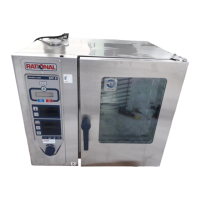
Type 6x1/1 GN, 10x1/1 GN
• Power supply terminal box with the corresponding
terminals is located on the bottom side underneath the
control panel.The terminals can be accessed by the
removeable cap. pic. 1
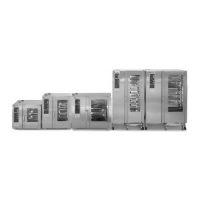
Type 10x2/1 GN, 20x1/1 GN, 20x2/1 GN
• Remove left-hand side panel pic. 2
• The supply terminals are located behind the removable
left-hand side panel.
Connection of mains:
• Connect an H07RN-F supply cable (minimum) and secure
the PG screws (strain relief) tight
• Connect the supply as follows:
Grey terminal: L1, L2, L3 (non-phase-sequence-dependent)
Blue terminal: Neutral (3N AC only)
Yellow-green terminal: Earth
• The circuit diagram is located behind the control panel.
• Other voltages available on request.
For appliance connections, precise dimensions and
connection points, see pages 84 to 95.
For legend, see pages 86 to 95:
1 = Shared water supply (cold water)
2 = Water supply, cold water
3 = Water supply, soft and warm water
4 = Drain
5 = Electrical connection
6 = Earth bonding
7 = Gas connection
F
Raccordement électrique
• Effectuer le raccordement des appareils conformément aux
consignes d‘installation et aux informations de la plaque
signalétique
• Suivre les spécifications VDE (Association des
Electrotechniciens Allemands) et les règles imposées par la
compagnie d‘électricité locale !
• Ligne électrique protégée par fusibles pour chaque appareil
• Nous vous recommandons l‘utilisation d‘un disjoncteur à
courant de défaut
• Prévoir un dispositif de coupure omnipolaire accessible
avec intervalle de contact d‘au moins 3 mm.
• Raccorder l‘appareil à une liaison équipotentielle.
• Caractéristiques de raccordement électrique,voir page 84:
• La section des lignes de raccordement est fonction de la
puissance absorbée et des dispositions locales.
• Normes applicables : EN 60335, IEC 335
• Modèles 6x1/1 GN: Cet appareil est approprié à un
fonctionnement raccordé à un réseau d’alimentation en
courant d’une impédance inférieure à 0,32 Ohms au point
de branchement au secteur. Le cas échéant, se renseigner
sur l’impédance du réseau auprès de l’entreprise
d’approvisionnement en électricité locale.
Modèles 6x1/1 GN, 10x1/1 GN
• Le coffret de raccordement au secteur avec les bornes
d’alimentation se trouve sur la partie inférieure de
l’appareil. L’accès s’effectue par le couvercle amovible par
l’avant. Fig. 1
Modèles 10x2/1 GN, 20x1/1 GN, 20x2/1 GN
• Retirer la paroi latérale gauche Fig. 2
• Les bornes sont situées derrière cette paroi latérale gauche
amovible.
Raccordement au secteur :
• Raccorder des câbles d‘alimentation de type H07RN-F
minimum et serrer à fond les raccords (décharge de
traction)
• Raccorder la ligne selon le schéma suivant :
bornes grises : L1, L2, L3 (indépendant du champ
magnétique rotatif)
borne bleue : neutre (uniquement 3N CA)
borne jaune-verte : terre
• Le schéma des circuits se trouve également derrière le
panneau de commande.
• Tensions spéciales sur demande.
Raccordements des appareils, cotage précis et points
de raccordement, voir pages 84 à 95.
Légende des pages 86 à 95:
1 = Alimentation commune en eau (eau froide)
2 = Alimentation en eau froide
3 = Alimentation en eau adoucie ou en eau chaude
4 = Evacuation des eaux usées
5 = Raccordement électrique
6 = Liaison équipotentielle
7 = Raccordement du gaz