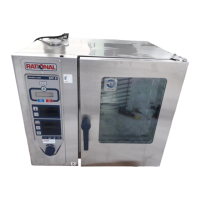
Do you have a question about the Rational CD Series and is the answer not in the manual?
Minimum clearance of 50 mm on left, right, and rear sides.
Minimum clearance of 350 mm when heat sources are on the left side.
Recommended 500 mm clearance on the left for service work.
Minimum clearance of 50 mm on left, right, and behind.
Minimum clearance of 350 mm from heat sources on the left-hand side.
Recommended 500 mm clearance on the left for servicing.
Minimum clearance of 50 mm on left, right, and behind.
Minimum clearance of 350 mm from heat sources on the left-hand side.
Recommended 500 mm clearance on the left for maintenance.
Minimum clearance of 50 mm on left, right, and rear.
Minimum clearance of 350 mm from heat sources on the left side.
Recommended 500 mm clearance on the left for repair and maintenance.
Minimum clearance of 50 mm on left, right, and rear.
Minimum clearance of 350 mm from heat sources on the left side.
Recommended 500 mm clearance on the left for maintenance.
Minimum clearance of 50 mm on left, right, and rear.
Minimum clearance of 350 mm from heat sources on the left side.
Recommended 500 mm clearance on the left for servicing.
Minimum clearance of 50 mm on left, right, and rear.
Minimum clearance of 350 mm from heat sources on the left side.
Recommended 500 mm clearance on the left for maintenance.
Minimum clearance of 50 mm on left, right, and rear.
Minimum clearance of 350 mm from heat sources on the left side.
Recommended 500 mm clearance on the left for servicing.
Gas appliances are fixed to the floor using a supplied set.
Electric appliances require a separate fixing set, not included.
Gas appliances are fixed to the floor using the supplied fixing set.
Electric appliances require a separate fixing set, not included.
Gas appliances are fixed to the floor using the supplied fixing kit.
Electric appliances: fixing kit is not part of the delivery.
Gas appliances include a fixing kit for the lower frame.
Electric appliances do not include the fixing kit in the supply.
Fix floor locks to the floor using screws, dowels, or adhesive.
Slide the unit stand into the floor locks.
Fix floor locks to the floor with screws, pins, or adhesive.
Slide the stand into the floor locks.
Fix floor locks using screws, dowels, or special adhesive.
Slide the unit into the floor locks.
Fix floor locks to the floor using screws, dowels, or special adhesive.
Insert the stationary unit into the floor lock receivers.
Secure unit feet to floor using supplied special stickers.
Slide the stand into the leg locks.
Fix floor locks using screws, dowels, or special adhesive.
Slide the unit into the floor locks.
Fix floor locks using screws, dowels, or special adhesive.
Insert the vertical model unit into the retainers.
Secure floor locks with screws, dowels, or adhesive.
Slide the fixed appliance into the foot locks.
Anchor floor locks with screws or bolts, or adhesive.
Slide the stand into the anchors.
Connect supply cable, follow schema for grey, blue, yellow-green terminals.
Connect H07RN-F cable, follow schema for grey, blue, yellow-green terminals.
Connect H07RN-F cable, follow schema for grey, blue, yellow-green terminals.
Connect H07RN-F cable, follow schema for grey, blue, yellow-green terminals.
Connect H07RN-F cable, follow schema for grey, blue, yellow-green terminals.
Follow installation instructions, VDE, supplier rules. Use RCD, isolation switch, earth bonding. Comply with EN 60335, IEC 335.
Details for 6x1/1, 10x1/1, 10x2/1 GN gas units. Terminal box, cable supply, polarity, color coding.
Follow installation instructions, rating plate info, local regulations.
Requires fused supply, earth leakage breaker, isolation device, earth bonding. Standards: EN 60335, IEC 335.
Details for 6x1/1, 10x1/1, 10x2/1 GN gas units. Terminal box, cable supply, polarity, color coding.
Connect according to installation instructions and rating plate.
Observe VDE norms, use fused lines, ground fault protection, isolation device.
Details for 6x1/1, 10x1/1, 10x2/1 GN gas units. Terminal box, cable supply, polarity, color coding.
Connect according to installation instructions and rating plate.
Observe VDE norms, use own fused supply, protective switch, isolation switch.
Details for 6x1/1, 10x1/1, 10x2/1 GN gas units. Terminal box, cable supply, polarity, color coding.
Connect according to installation instructions and rating plate.
Use own fused supply, RCD, isolation switch, earth bonding. Standards: EN 60335, IEC 335.
Details for 6x1/1, 10x1/1, 10x2/1 GN gas units. Terminal box, cable supply, polarity, color coding.
Measure exhaust gases (CO, CO2) during commissioning. Adjust burners if CO > 1000ppm.
Analyze waste gas (CO, CO2) during commissioning. Adjust burners if CO > 1000 ppm.
Measure exhaust gases (CO, CO2) during commissioning. Adjust burners if CO > 1000ppm.
Measure exhaust gases (CO, CO2) during commissioning. Adjust burners if CO > 1000ppm.
| Brand | Rational |
|---|---|
| Model | CD Series |
| Category | Electric Steamer |
| Language | English |