Page 12 of 37
INSTRUCTION, USE AND
MAINTENANCE MANUAL
GB
• Execute 4 holes with 12 mm diameter on the floor
by the holes on the bottom floor;
• insert the small blocks (excluded from supply) into
the holes;
• fix the machine to the ground with 4 M12x120 mm
screws (excluded from supply) (Fig. 5 ref. 1) (or
with 4 12x80 mm stud bolts (excluded from supply)).
Tighten the screws with an approximate tightening
torque of 70 Nm.
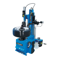
• Before clamping completely the machine to the floor,
level its rear part rotating the feet (Fig. 6 ref. 1).
1
Fig._6
9.2 Fixtures contained in the packing
The packing case contains also the fixtures box.
Check that all the parts listed are there.
Code Description N.
B1157000 Two-faced cone 1
710013421 Reverse wheels protection 1
710012941 Entrainer pin extension 1
710090481 Pin protection 1
790011620 Bead sliding foil 1
790011640
Instructions for bead sliding
foil
1
710590840 Bead insertion belt kit 1
9.3 Assembly procedures
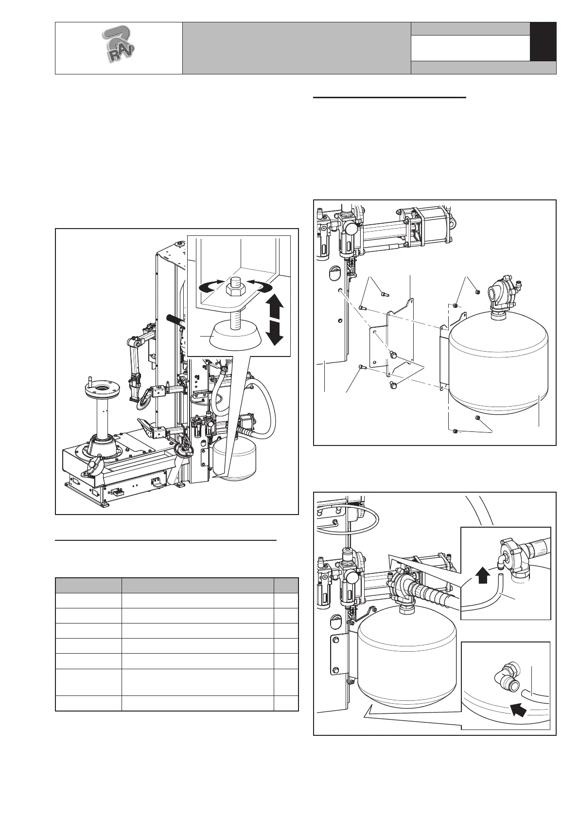
1. Assemble “Tubeless inflation” unit to the machine
keeping to the following instructions:
- fix the tank (Fig._7 ref._6) to the support flange
(Fig._7 ref._2) using the screws (Fig._7 ref._4)
and nuts (Fig._7 ref._5) equipped on issue;
- fix the flange (Fig._7 ref._2) to the machine (Fig._7
ref._3) using the screws (Fig._7 ref._1);
1
2
3
4
4
5
5 6
Fig._7
2. Connect the black pipe (Fig._8 ref._1) and the blue
pipe (Fig._8 ref._2) on the provided quick couplings
as shown in Figure 8.
1
2
Fig._8
3. Mount the grease bucket holder ring (# 0223000)
(Fig._9 ref._1), in the fixture box, using the 2 screws
provided (Fig._9 ref._2) to the machine body (Fig._9
ref._3).
G1180.30SLIM - G1180.30SLIMIT
7105-M002-10_R
RAVAGLIOLI S.p.A.
 Loading...