Page 14 of 37
INSTRUCTION, USE AND
MAINTENANCE MANUAL
GB
10.1 Working area modification
After the delivery, the machine is prearranged to op-
erate on wheel of 50” maximum diameter and a rim
diameter (10” - 30”). It’s also possible to move the tools
column to enlarge the working area from 52” (with rim
diameter of 12” - 32”) up to 54” (with rim diameter of
14” - 34”) (see Figure 12).
Fig._11
A
B
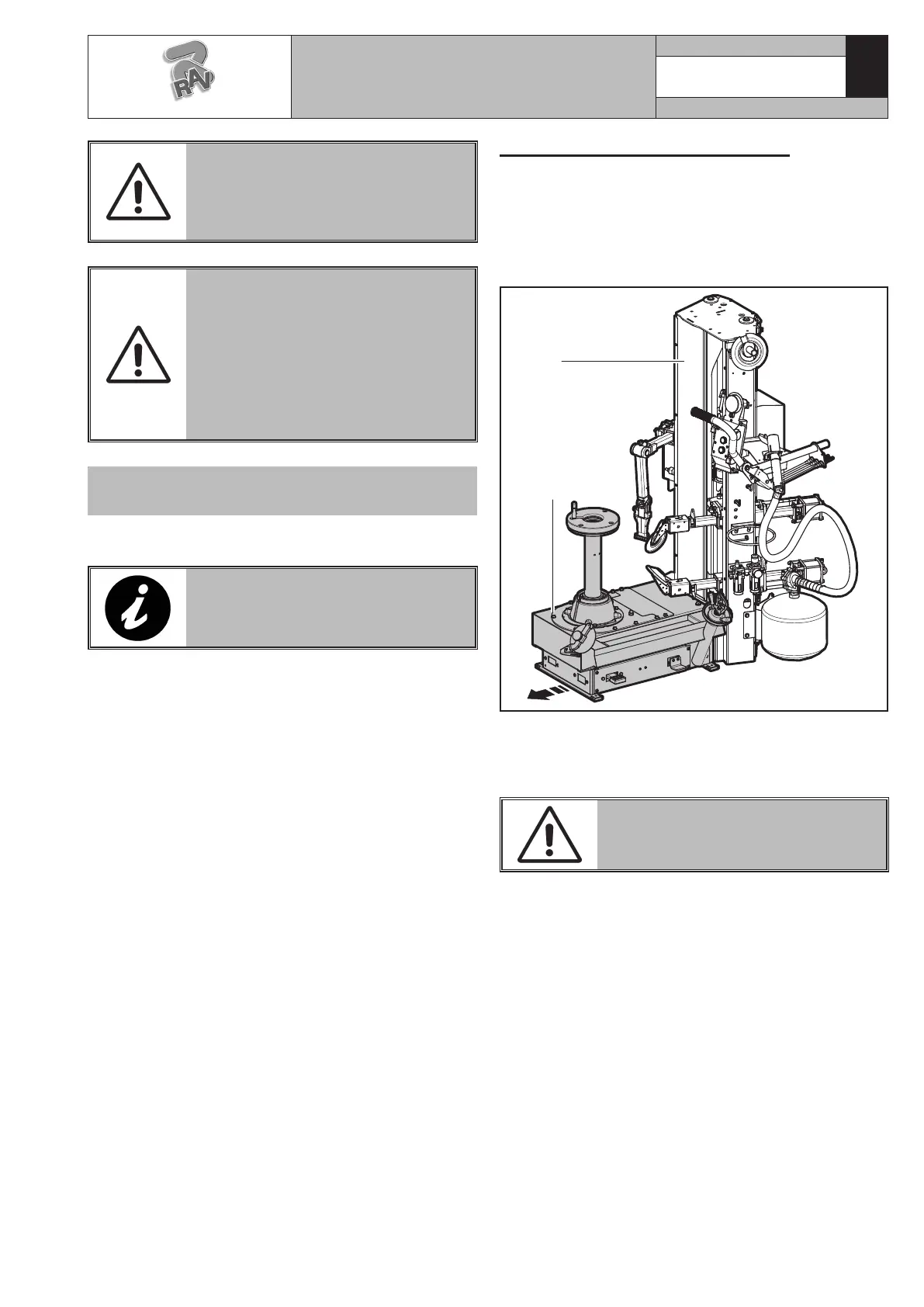
The column is moved by unloosing the fixing screws of
the base (Fig._11 ref._A) to the column (Fig._11 ref._B)
and by sliding the base (Fig._11 ref._A) itself into the
proper slots until the required measure.
MAKE SURE THE TYRE-CHANGER
COLUMN IS STABLE: USE A CA-
BLE, HELD BY A HOIST.
1. Remove the lateral guards (Fig._12 ref._1-2) of the
machine.
2. Unscrew the screws (Fig._12 ref._3) and the nuts
near the central slots (Fig._12 ref._4) paying atten-
tion not to remove the nuts from the proper screws.
3. Remove the six remaining screws (Fig._12 ref._5).
4. Move the base (Fig._12 ref._6) into the required
position (to 43” or 45”) and if necessary, use a lift-
ing device.
5. Lock the base three screws (Fig._12 ref._3) with a
couple of 80 Nm.
6. Place six screws (Fig._12 ref._5) previously removed
and lock them on the bases side with a couple of
80 Nm.
7. Assemble again the lateral guards (Fig._12 ref._1-2)
of the machine.
FIT A TYPE-APPROVED PLUG
TO THE MACHINE CABLE (THE
GROUND WIRE IS YELLOW/GREEN
AND MUST NEVER BE CONNECT-
ED TO THE PHASE LEADS).
MAKE SURE THAT THE ELECTRI-
CAL SYSTEM IS COMPATIBLE
WITH THE RATED POWER AB-
SORPTION SPECIFIED IN THIS
MANUAL AND APT TO ENSURE
THAT VOLTAGE DROP UNDER
FULL LOAD WILL NOT EXCEED
4% OF RATED VOLTAGE (10%
UPON START-UP).
VERSION WITH
SINGLE-PHASE MOTOR
On delivery, the machine is pre-set to operate at a
single-phase voltage of 200 ÷ 265 V - 50/60 Hz.
FAILURE TO OBSERVE THE ABOVE
INSTRUCTIONS WILL IMMEDIATE-
LY INVALIDATE THE WARRANTY.
G1180.30SLIM - G1180.30SLIMIT
7105-M002-10_R
RAVAGLIOLI S.p.A.
 Loading...