Page 21 of 37
INSTRUCTION, USE AND
MAINTENANCE MANUAL
GB
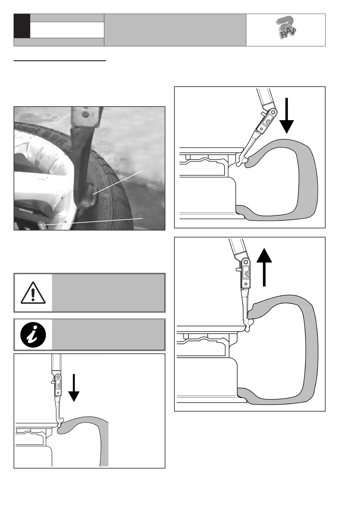
3. Move forward the tool so that it penetrates between
rim and tyre (see Fig._29). While this operation is
being effectuated, the tool rotates around the rim
edge until it hooks the tyre bead (see Fig._30).
Fig. 29
Fig. 30
4. Lift the tool using the control provided (Fig. _13
ref._I). When the tool reaches a vertical position
related to the rim (Fig._31 ref._1), rotate the man-
drel so that the tyre enters the rim groove. Keep on
raising the tool until the bead is on the rim edge
(see Fig._30).
12.5 Demounting the tyre
When both beads are broken, the tyre can be de-
mounted.
1. Press the pedal (Fig._14 ref._A) to rotate the wheel
clockwise until the valve stem reaches “hour 1”
position (Fig._27 ref._1).
1
2
Fig. 27
2. Position the upper tool (Fig._27 ref._2) just next
the rim edge using the control provided (Fig._13
ref._H) (tool descent) (see Fig._28). While this phase
is being carried out, stay just next to a zone in the
tyre where bead breaking has been effectuated.
MOVE VERY CAREFULLY THE
TOOLS HOLDER ARM TO WORK-
ING POSITION, IN ORDER TO
AVOID POSSIBLE HANDS CRUSH-
ING.
USE ONLY TYRE LUBRICANTS.
SUITABLE LUBRICANTS CONTAIN
NO WATER, HYDROCARBONS, OR
SILICON.
Fig. 28
7105-M002-10_R
RAVAGLIOLI S.p.A.
G1180.30SLIM - G1180.30SLIMIT
 Loading...