3030
0579-M090-0
RISERVATO AL PERSONALE AUTORIZZATO ALL'INSTALLAZIONE - ONLY FOR INSTALLATION-AUTHORIZED STAFF
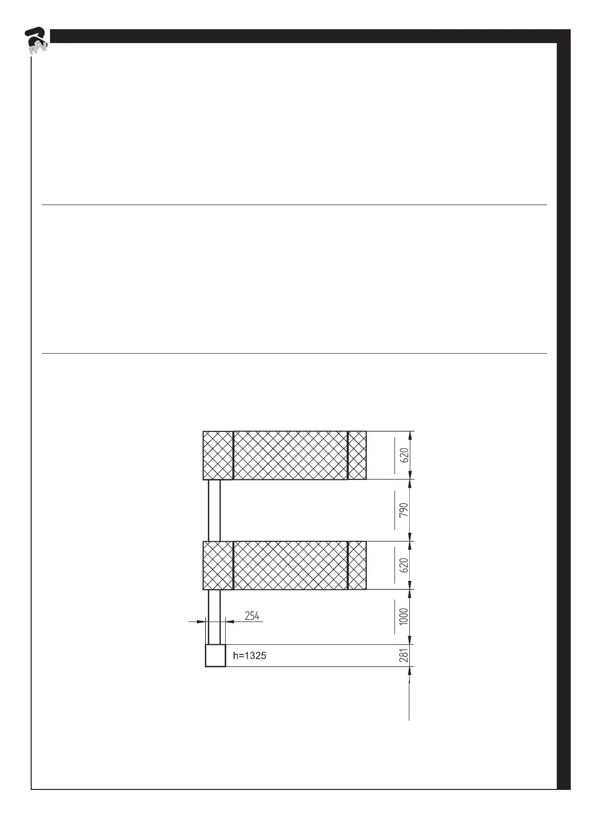
4.4 Posizionamento delle pedane e collegamento dell'impianto in posizione standard RAV540U
Posizionare le pedane e il mobiletto di comando (vedi Fig. 9) alla giusta distanza fra loro tenendo presente che i cilindri P1A e
P1B, aventi diametro maggiore, si dovranno trovare all'interno del ponte (vedi Fig. 10).
Estrarre da sotto la pedana A, posta vicina alla centralina, i quattro tubi indicati con 1, 2, 3 e 4, togliere i rispettivi tappi e collegarli
alla centralina come si vede in Fig. 10.
Sostituire nella centralina idraulica il tappo-asta di livello 5. Verificare che il livello dell'olio sia circa a 10 mm (3/8") dal tappo stesso.
Fig. 9
RAV540U
2' 13/32"2' 13/32" 2' 7 3/32"
(10")
3' 3 3/8"
(11 1/16")
(4' 4 5/32")
4.4 Positioning the footboards and connecting the system in the standard position RAV540U
Position footboards and control cabinet (see Fig. 9) at the right distance from each other, keeping in mind that cylinders P1A and
P1B, which feature a bigger diameter, will have to be inside lift (see Fig. 10).
Extract from underneath footboard A, located near the control unit, the four pipes indicated with 1, 2, 3 and 4, remove the relevant
caps and connect them to the control unit as shown in Fig. 10.
Replace the plug-dipstick 5 in the hydraulic unit. Check that the oil level is about 10 mm (3/8") from the plug itself.
 Loading...