EasyManua.ls Logo

Raymarine 400G User Manual

Raymarine 400G
40 pages
To Next Page IconTo Next Page
Page #1 background imageLoading...
Page #1 background image
T150/150G/T400/400G Course Computers
Type 150/150G/400/400G Course Computers Service Manual 83156-1 1
Type 150/400 Course Computers
T150, 150G, T400 and 400G
Autopilot Course Computers
Service Manual
Document Number: 83156-1
Date: July 2002
Course Computer core packs
(including compass and rudder reference)
E12054, T150 core pack
E12055, T400 core pack
E12091, 150G core pack
E12092, 400G core pack
Course Computer only
E15013, T150 Course Computer
E15014, T400 Course Computer
E15015, 150G Course Computer
E15016, 400G Course Computer
WARNING:
CE Marking of Equipment/Replacement Parts
If the Raymarine equipment under repair, test, calibration, installation or setting to work carries the European CE mark,
only parts and components supplied or approved for such use by Raymarine should be used in order to maintain
compliance with the relevant CE requirements.
Incorporation, use or attachment, by any means, of parts or components not supplied for or not approved for such use by
Raymarine or, if supplied or approved for use by Raymarine, not properly fitted in accordance with instructions
published, provided or recommended by Raymarine, may cause the equipment to malfunction and, in particular, to
become unsafe or to no longer meet the relevant CE requirements. In these circumstances, Raymarine excludes liability
to the fullest extent permissible in law for any loss or damage including any liability for its contribution to such loss or
damage by its negligent acts or omissions.

Table of Contents

Question and Answer IconNeed help?

Do you have a question about the Raymarine 400G and is the answer not in the manual?

Raymarine 400G Specifications

General IconGeneral
Rudder FeedbackYes
Power Supply12V or 24V DC
InterfaceNMEA2000
Drive UnitHydraulic drive unit
SystemAutopilot System

Summary

Chapter 1: Introduction

1.1. General description

Overview of the autopilot course computer's function and components.

1.2. Variants

Details the differences between the four course computer models.

Chapter 2: Main Parts and Spares

2.1. Type 150/150G spares

Lists spare parts and accessories for Type 150/150G models.

2.2. Type 150/150G exploded view

Visual breakdown of Type 150/150G components with part numbers.

2.3. Type 400/400G spares

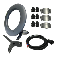
Lists spare parts and accessories for Type 400/400G models.

2.4. Type 400/400G exploded view

Visual breakdown of Type 400/400G components with part numbers.

2.5. Spares packs for 150/150G/400/400G

Details available spares packs for all course computer variants.

Chapter 4: Disassembly and Reassembly

Detailed Diagnosis

Step 1 - Power Checks

Verifies correct voltage readings at various test points.

Step 2 - System Checks

Checks display and Seatalk communication functionality.

Step 3 – Rate Gyro (if fitted)

Tests the functionality of the internal rate gyro.

Step 4 – Compass

Verifies compass heading response to rotation.

Step 5 – Rudder Reference

Checks rudder reference input and display movement.

Step 6 – Clutch (Auto)

Measures clutch voltage in AUTO mode.

Step 7- Clutch (Standby)

Measures clutch voltage in STANDBY mode.

Step 8- H-Bridge

Tests motor direction and speed control via H-Bridge.

Step 9 – NMEA

Checks NMEA data input and output via serial ports.

Step 10 – Kill Switch

Verifies shutdown response to the kill switch.

Step 11 – EEPROM Test

Checks calibration settings storage in EEPROM memory.

Related product manuals