Chapter 6: Installation 6-1
Introduction
Chapter 6: Installation
6.1 Introduction
This chapter provides installation instructions for your SL520/530/631 PLUS
display. Details for mounting the SL520/530/631 PLUS display and
connecting the equipment are included.
• To install display unit follow the instructions in Section 6.2 to Section 6.6.
ou should then test the display as described in Section 6.7.
• To connect your display to other equipment, follow the guidelines in
Section 6.8 and Section 6.9, taking particular care to ensure the correct
polarity of the SeaTalk supply.
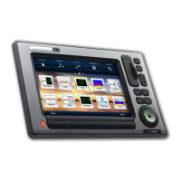
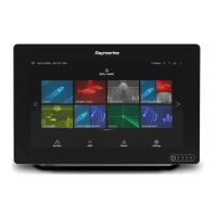
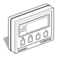
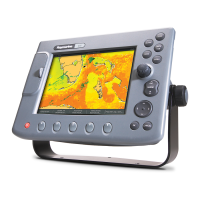
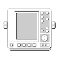
Figure 6-1: Typical Chartplotter System
Note: If you wish to practice using the display before installation, connect a
12V or 24V DC power supply (connecting the red wire via a 6.3A quick blow
fuse to positive and the black wire to negative) and using the simulator mode,
as described in Chapter 2.
NMEA
SeaTalk
Display Unit
Distribution Panel
D4288-1
12/24V Supply
12V Supply
12V Supply
Junction
Box
GPS
Compass
 Loading...