26
NOTE: To avoid water damage or scalding due to
valve operation, drain pipe must be connected to valve
outlet and run to a safe place of discharge. Drain pipe
must be the same size as the valve discharge connec-
tion throughout its entire length and must pitch down-
ward from the valve. No shut-off valve shall be
installed between the relief valve and the drain line.
Valve lever should be tripped at least once a year to
ensure that waterways are clear.
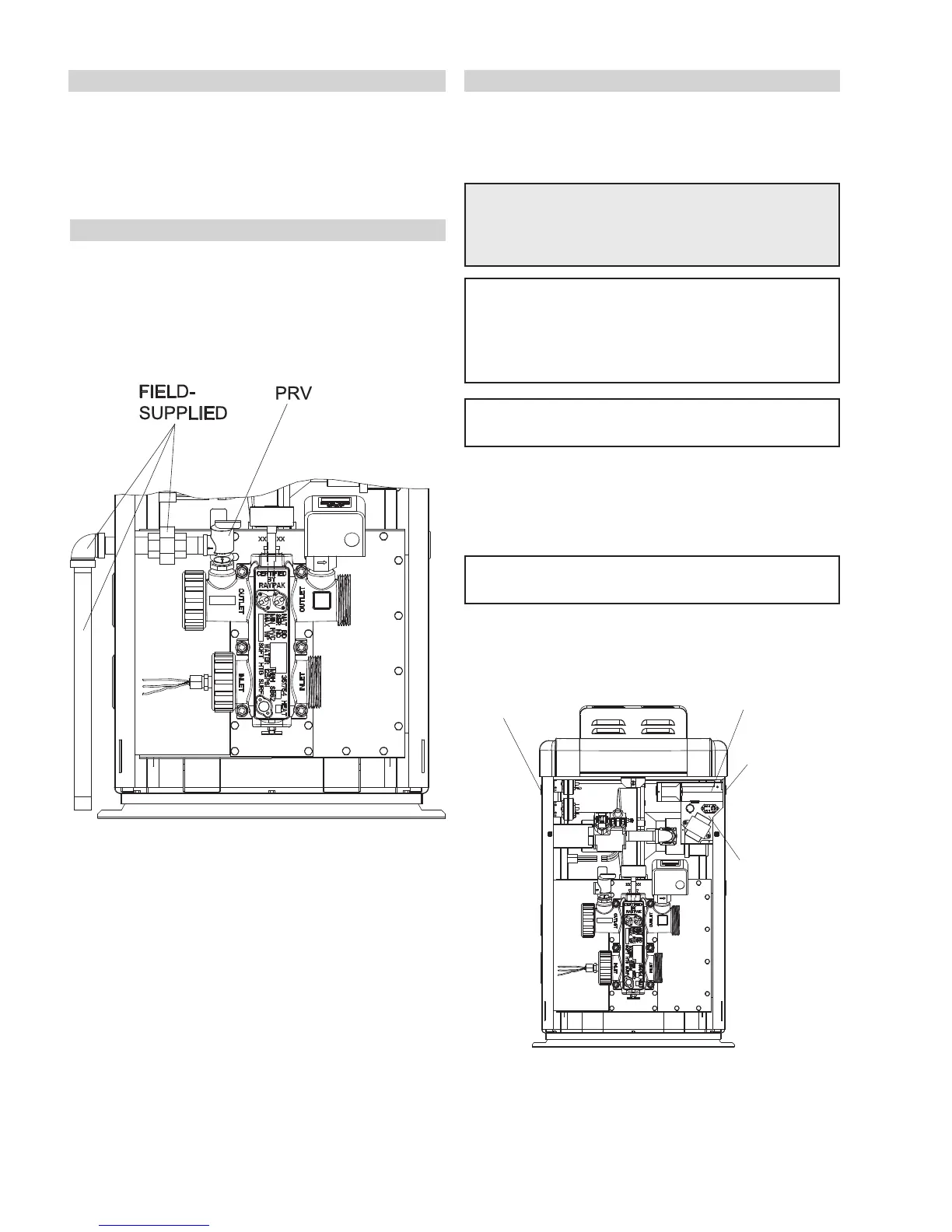
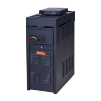
PRESSURE RELIEF VALVE INSTALLATION
To conform to local building codes, it may be neces-
sary to install a 3/4" pressure relief valve, having a
capacity at least equal to the BTUH output of the
model. The maximum acceptable pressure relief valve
setting is 125 psi.
ELECTRICAL WIRING
NOTE: If it is necessary to replace any of the original
wiring, use 105°C wire or its equivalent, and/or 150°C
wire or its equivalent, like the original wiring.
WARNING: Heaters are factory-wired for
240VAC power supply. DO NOT attempt to oper-
ate with a 208VAC nominal supply.
CAUTION: Heater must be electrically grounded and
bonded. Bonding lug is provided loose with the
heater. Install bonding lug on lower right or left side
of jacket as necessary for bonding the heater.
Mounting hole is provided on the jacket.
The Electronic Intermittent Ignition Device automati-
cally lights the main burner upon a call for heat. The
heater is supplied with a dual-voltage transformer for
120 VAC or 240 VAC input power hookup.
NOTE: Failure to ground the heater electrically
could affect the heater’s electronics.
NOTE: See page 40 for further instructions if using
a time clock/fireman’s switch.
Wiring locations
CONTROL BOX
(FACTORY-MOUNTED
LOCATION)
FIELD WIRING BOX
RECOMMENDED
POWER SUPPLY
SIDE
OPTIONAL
POWER SUPPLY SIDE
(ROUTING TO WIRING
BOX REQUIRED)
AUXILIARY BYPASS VALVE ADJUSTMENT
To set bypass: With clean filter, adjustment is made by
feeling the inlet and outlet pipes at the heater. Outlet
pipes should be slightly warmer than inlet and comfort-
able to the touch. If pipe is hot, close bypass; if cold,
open bypass.