Do you have a question about the Raypak AVIA 264 and is the answer not in the manual?
Table detailing recommended water chemistry levels for different pool and spa types.
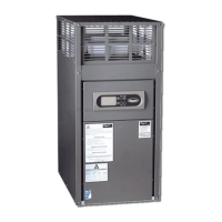
Specifies the location of model and serial numbers on the product's packaging.
Indicates an alternative location for model and serial numbers on the unit's front.
Identifies the location of the model and serial number on the unit's rating plate.
Specifies required clearances for installing the heater indoors.
Specifies required clearances for installing the heater outdoors.
Warning against installing the heater close to sprinkler systems.
Prohibits installation near heat pumps or outdoor condensing units.
Details requirements for ventilation and combustion air openings for indoor installation.
Table showing maximum pipe lengths for natural gas and propane based on BTU input.
Lists potential issues caused by insufficient gas pressure.
Specifies required gas pressures for natural and propane gas operation.
Illustrates an incorrect method for installing a gas line sediment trap.
Illustrates the correct method for installing a gas line sediment trap.
Diagram of the circuit board for Model 264.
Diagram of the circuit board for Model 404.
Illustrates the common wiring connections for the heater components.
Diagrams the wiring for a 120VAC power supply.
Diagrams the wiring for a 240VAC power supply.
Details the 240V jumper and blower connections for the heater.
Details the 120V jumper and blower connections for the heater.
Explains the function and terminals of the auxiliary output.
Provides terminal, wire, and rating information for the auxiliary relay.
Illustrates wiring the auxiliary output with an external power supply.
Illustrates wiring the auxiliary output using a 24VAC transformer.
Illustrates wiring the auxiliary output to a 3-way valve actuator.
Describes the sequence of displays shown during the heater's startup.
Explains the functions of the UP, DOWN, SERVICE, and MODE buttons.
Describes displays indicating unit heating and demand fulfillment.
Explains the 'No Demand' display when set temperature is met.
Outlines the initial steps for powering the heater.
Details the 24 VAC application to the ignition and gas control.
Describes the heating process involving spark and gas valve activation.
Explains wiring options for remote switching functions.
Displays and procedures for operating the heater remotely.
Steps to enable remote operation via the control pad.
Indicates improper remote wiring and its consequences.
Illustrates proper wiring for pool and spa remote connections.
Lists and describes common self-diagnostic messages on the LCD.
Provides troubleshooting steps and recovery methods for faults.
Describes LCD messages indicating temperature sensor faults.
Identifies the inlet and outlet temperature sensors and their part numbers.
Explains the low-temperature lockout condition and its implications.
Details lockout conditions related to over-temperature and flue issues.
Flowchart for initial power-on and display lit checks.
Flowchart for identifying and responding to fault messages.
Flowchart detailing blower operation and heating sequence.
Lists common faults and their corresponding troubleshooting steps.
Illustrates and lists key components of the safety circuit.
Describes display messages for various safety switch faults.
Provides guidance on troubleshooting common safety switch faults.
Explains the function of the fireman's switch.
Details vent temperature sensor monitoring and fault conditions.
Provides access to basic service and diagnostic information.
Details access to advanced service menus and their functions.
Explains how to view recent service displays and fault history.
Instructions for clearing the fault history.
Steps to enter the Program Mode for settings adjustment.
Lists and describes various programmable settings and functions.
Procedure for activating the control lockout feature.
Procedure for deactivating the control lockout feature.
Identifies water pressure switch and bypass assembly components.
Identifies temperature sensors and Unitherm Governor components.
Explains the Unitherm Governor's role in preventing condensation.
Provides a tech tip for testing the Unitherm Governor's function.
Describes the ProTek Shield's role in galvanic corrosion protection.
Step-by-step instructions for replacing the ProTek Shield Assembly.
Table showing pressure drops across the heat exchanger at various flow rates.
Table indicating minimum and maximum flow rates for different models.
Explains how the automatic bypass assembly adjusts flow rate.
Table for correct bypass spring selection based on model.
Illustrates correct installation of a pressure relief valve (PRV).
Step-by-step guide for removing the igniter.
Table detailing gas orifice types and their usage for different gas sources.
Describes the functions of vent, differential, and air pressure switches.
Chart for identifying and selecting the correct air pressure switches.
Steps for signing up and creating an account for the Raymote app.
Instructions for powering on the AVIA heater.
Procedure for adding the AVIA heater as a new device in the app.
Steps for connecting the AVIA heater to the Raymote app.
Instructions for selecting Wi-Fi network and entering password.
Visual indication of the AVIA heater connecting to Wi-Fi.
Steps to name the heater and finalize Raymote control setup.
Provides suggestions for improving Wi-Fi signal strength.
Provides phone numbers and email addresses for technical support.
Details different support categories and their contact points.
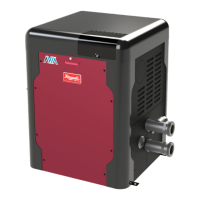
| Model | AVIA 264 |
|---|---|
| Category | Swimming Pool Heater |
| Heating Capacity | 264, 000 BTU/hr |
| Fuel Type | Natural Gas or Propane |
| Voltage | 120V |
| Heat Exchanger Material | Cupro-Nickel |
| Ignition Type | Electronic |
| Water Connection Size | 2 inches |
| Warranty | 2 years |