If you see a number “3,” it means the Normally High setpoint will change
state when the target temperature or value exceeds the alarm value. If a
number “2” displays, the Normally High setpoint will change state when
the target temperature or value is lower than the setpoint alarm value.
Note that the “O” and “L” indicators on the monitor are controlled by SP1
and SP2. The “L” lights when the input signal has fallen below either the
SP1 or SP2 value and when the trigger level (“b”) is set to either “0” or
“2”. The “O” indicator lights when the input signal has risen above either
the SP1 or SP2 value and when the trigger level (“b”) is set to either “1” or
“3”. Figure 10 (below and continued on next page) shows examples of
how the setpoints change state when triggered.
O
N
L
C
F
Thermalert GP
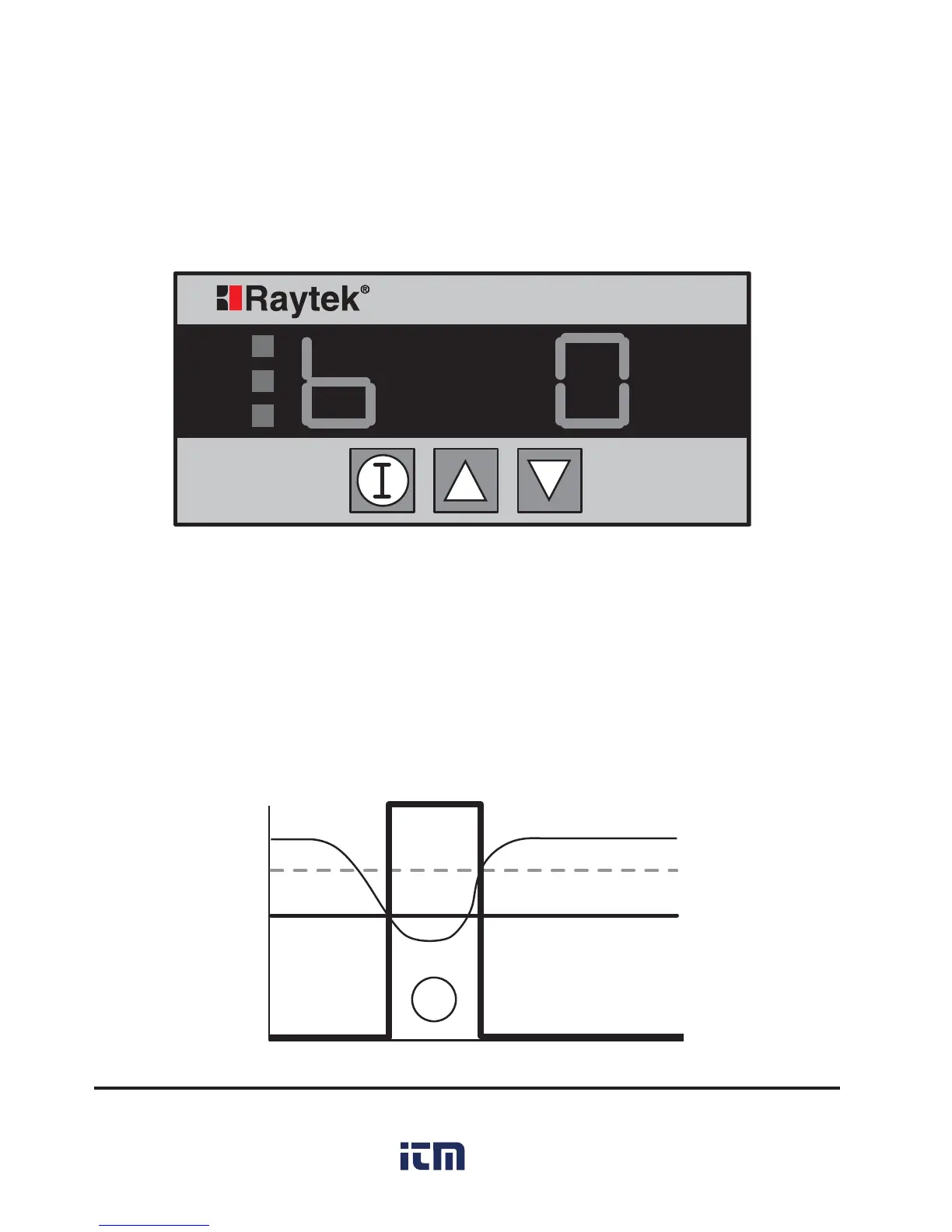
Figure 9: Setpoint Alarm (Trigger) Display

 Loading...