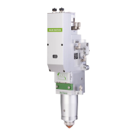
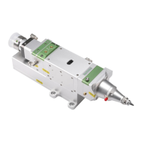
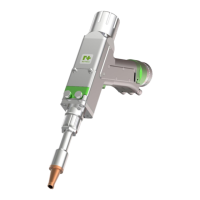
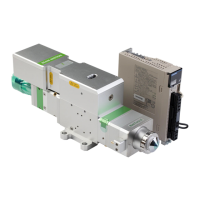
The BM111 series laser heads are auto-focusing cutting heads for fiber lasers, released by Switzerland RAYTOOLS AG in 2017. These products are equipped with internal servo motor drive units that use a linear mechanism to automatically drive the focusing lens to change position within a range of approximately 22mm. Users can program settings to achieve continuous adjustment of the focus position, enabling rapid perforation of thick plates and automatic cutting of materials with varying thicknesses. The BM111 series can be equipped with D30 composite lens groups to integrate the beam. Diversified interface configurations allow adaptation to a variety of fiber lasers, while optimized optical and water-cooled designs ensure continuous and stable operation under high power for extended periods.
Function Description:
The laser head consists of four basic units: a collimating module, a focusing driver module, a protective lens module, and a nozzle module.
- Collimating module: This module collimates the incident laser into a parallel beam and adjusts the beam spot to the center of the nozzle.
- Focusing driver module: The collimating beam is focused into a small beam spot with high power density, and the focus position is automatically adjusted by the driving device.
- Protective lens module: The protective lens shields the focusing lens from damage caused by returning slag, thereby extending the service life of the focusing lens.
- Nozzle module: This module guides the focused beam to the workpiece and produces a high-velocity jet for high-quality cutting.
Important Technical Specifications:
- Automatic focusing range: +10 to -12mm
- Adjustment accuracy: 0.05mm
- Maximum fiber power: Up to 3KW (when equipped with D30 composite lens groups)
- Maximum acceleration of focus lens driver: 10m/s²
- Maximum speed of focus lens driver: 10m/min
- Cooling water pipe diameter (outside diameter): 6mm
- Minimum cooling water flow speed: 1.8 l/min (0.48gpm)
- Cooling water entry pressure: 170-520kPa (30-60 psi)
- Cooling water entry temperature: ≥room temperature / > dew point
- Cooling water hardness (relative to CaCO3): < 250mg/liter
- Cooling water PH range: 6 to 8
- Cooling water particles size available: Diameter less than 200 microns
- Cutting gas pipe diameter (outside diameter): 10mm
- Cooling gas pipe diameter (outside diameter): 8mm
- Recommended cutting gas purity (Oxygen): 99.95% (Max water vapor <5 ppm, Max hydrocarbon <1 ppm)
- Recommended cutting gas purity (Nitrogen): 99.99% (Max water vapor <5 ppm, Max hydrocarbon <1 ppm)
- Recommended cutting gas purity (Argon): 99.998% (Max water vapor <5 ppm, Max hydrocarbon <1 ppm)
- Recommended cutting gas purity (Helium): 99.998% (Max water vapor <5 ppm, Max hydrocarbon <1 ppm)
- ETC_F100 Dimensions: 80mm (width) x 150mm (height) x 55mm (depth) for the main body, with a total length of 211.05mm including mounting.
Usage Features:
- Optimized optical configuration and smooth and efficient airflow design: Ensures superior cutting performance.
- Drawer-type lens mount: Facilitates quick and easy replacement of protective lenses.
- Composite lens groups: Used for beam collimating and focusing to achieve optimal optical quality and cutting effect.
- Fiber interfaces: Equipped with QBH, QD, and other interfaces to match various fiber lasers.
- Beam center position adjustment: Critical for cutting quality, adjusted by manipulating the collimating lens in X-Y directions using screws on top of the cutting head. A tape dotting method is commonly used to ensure the beam spot is centered in the nozzle.
- Beam focus position adjustment: Even with automated focusing, manual dotting is required to re-determine the focus position when replacing lenses or lasers. This involves setting laser power to 80-100W, making holes in textured paper at 0.5mm intervals, and identifying the smallest hole as the zero focus position.
- Mechanical installation: The laser head should be installed perpendicular to the process material surface and securely locked to ensure stable cutting. The Z-axis motor slide plate for fixing the laser cutting head should be well-grounded.
- Water-cooled system: Two sets of water-cooled channels are available, with arbitrary entry and exit directions. Water cooling is recommended for laser powers greater than 500 watts. A closed-loop water-cooled system is designed, but external water supply can be used if requirements are met.
- Assist gas interface: Impurities in cutting gas (hydrocarbons, water vapor) can damage lenses and affect laser power. High-purity gas is recommended, and stainless steel fittings should be used to prevent permeation of oxygen and water vapor. Filters capable of removing 0.01 micron particles are advised.
- Cable connection: Motor power, encoder, and sensor cables are connected to their respective interfaces on the cutting head and driver. All wiring must be done with the power off. The limiting sensor has a normally closed output mode.
- Fiber insertion: When inserting the optical fiber, ensure the red point on the QBH connector aligns with the red point on the handwheel. Remove the dust-proof cover, align the red mark of the fiber output end to the QBH red mark, insert the fiber interface straight to the bottom, then turn the QBH handwheel clockwise until a "Da" sound is heard. If misalignment occurs, loosen the four locking screws, rotate the QBH interface, and re-tighten. Optical devices must be kept clean, and dust removed before use. For vertical insertion, rotate the laser head 90 degrees horizontally to prevent dust from entering.
Maintenance Features:
- Regular lens cleaning: Essential due to the nature of laser cutting. Protective lenses should be cleaned weekly, while collimating and focusing lenses require cleaning every 2-3 months.
- Lens cleaning procedure: Involves wearing dust-proof gloves/finger sleeves, spraying ethanol on a polyester fiber cotton stick, gently holding the lens by its slide edge (avoiding touching the surface), and wiping in a single direction (bottom to top or left to right) to avoid secondary pollution. Both sides should be cleaned, ensuring no residues remain.
- Protective lens removal and installation: Loosen two locking screws, pull out the drawer-type lens mount, remove the pressure ring, and then the lens (wearing finger sleeves). Clean the lens, mount, and sealing ring. Replace the elastic sealing ring if damaged. Install the new cleaned lens, replace the pressure ring, and insert the mount back into the laser head, tightening the screws. Avoid pulling the elastic sealing ring directly to prevent damage.
- Collimating lens removal and installation: Perform in a clean environment. Remove the laser head and clean its surface. Use a 3mm inner hexagon spanner to loosen the screws of the collimating components and seal the connected part with crepe paper to prevent dust. Unscrew the collimating lens mount, remove the spring pressure ring and lens using a tool. Clean or replace the lens. Reassemble in sequence, ensuring the spring pressure ring is tightened properly. Tighten the locking screws and check the focus position.
- Focusing lens removal and installation: Perform in a clean environment. Remove the laser head and clean its surface. Place the laser head horizontally and remove the locking screws from bottom to top. Use a lens removing tool to remove the focus lens mount, then the spring pressure ring and focusing lens. Replace or clean the lens. Carefully place the focusing lens and spring pressure ring into the lens mount and tighten the pressure ring. Reassemble the components and check the focus position.
- Nozzle connection assembly replacement: If the laser head is hit during cutting, the nozzle connector may need replacement.
- Ceramic structure replacement: Unscrew the nozzle. Press the ceramic structure to ensure it's not skewed, then unscrew the pressure sleeve. Align the pinhole of the new ceramic structure with the locating pins, press it by hand, and screw the pressure sleeve. Screw the nozzle back and tighten it. After replacing the nozzle or ceramic structure, re-capacitance calibration is necessary.
- Nozzle replacement: Screw off the old nozzle, replace with a new one, and re-tighten. Re-capacitance calibration is required.
- Fault analysis (ETC_F100):
- Upper and lower limit alarm: Occurs when the Z-axis limit sensor signal is detected. Check connections, obstructions, installation, and signal disturbance. Ensure proper grounding and power filtering.
- "Zero returning" alarm: Occurs after power-off/restart if the controller hasn't returned to zero. Can be resolved by performing a zero return operation via ETC_F100, enabling automatic zero return on power-on, or inputting a high-level signal through the "Zero returning" interface.
- "Exceeding z-axis stroke" alarm: Generated when the Z-axis coordinate exceeds its travel. Check Z-axis travel settings and dial overtravel location.
- "Servo Alarm": May indicate incorrect servo driver wiring or external interference if the drive is normal.
- "Servo Calibration" process terminated abnormally: Occurs if the dial is at or near the upper limit during calibration. Move the dial to the middle of the stroke (more than 1mm) before recalibrating.
- Abnormal screen display: External interference can cause this; reboot ETC_F100.
- Z-axis coordinate offset: If the Z-axis coordinate changes slowly in a static state, restart servo calibration.
- Input signal jitter or invalid: Check I/O port detection interface. Connect 24V (active high) or 0V (active low) to the input port to verify signal inversion. Ensure 24V power of the input signal is common ground with ETC_F100 power supply to remove interference.