nne
co
er tu
e gas
o
ers
water
eaters –
o
er
anua
16
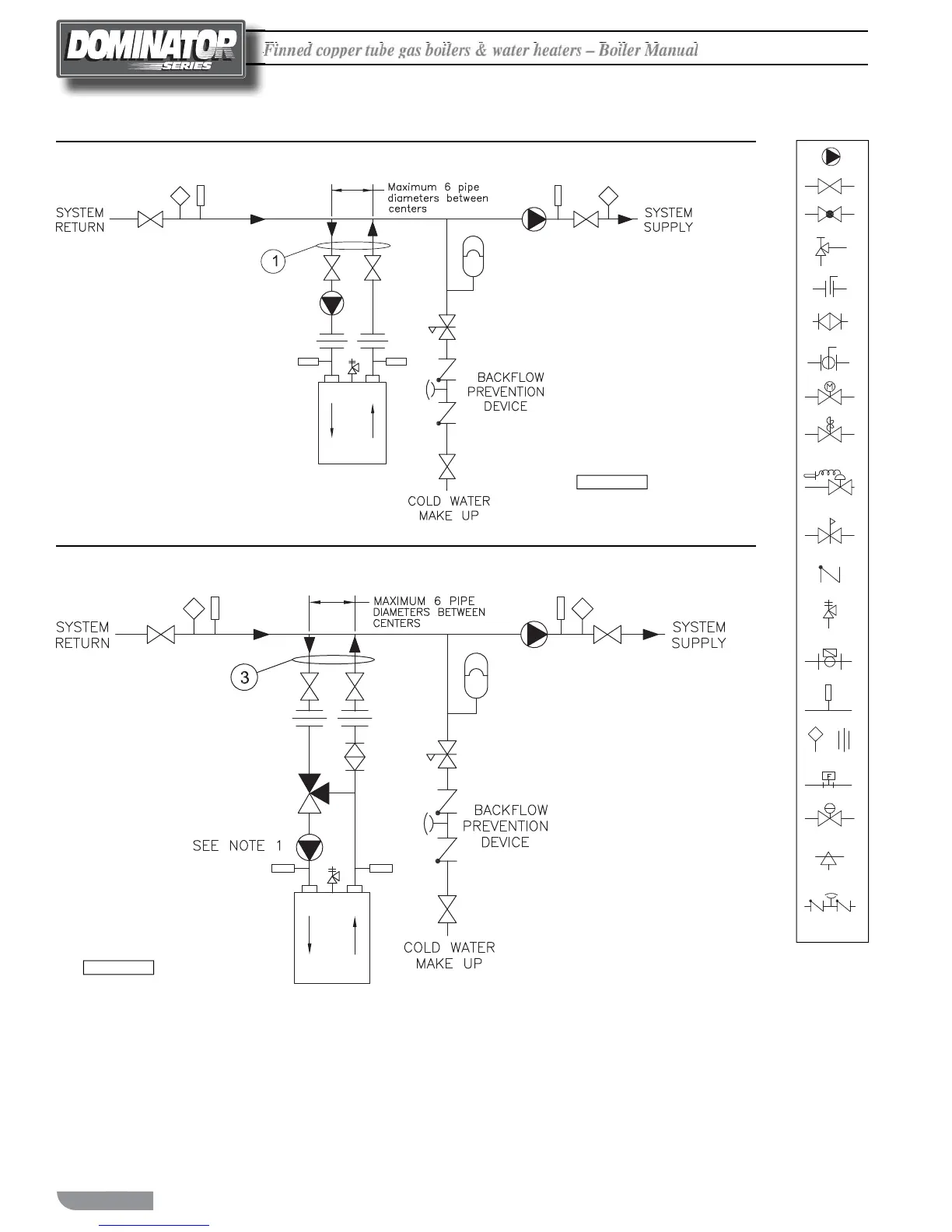
Figure 11 Typical Primary/Secondary Piping
(See Notes)
Figure 12 Low Temperature Piping with Thermostatic Valve
(See Notes)
Operated Valve
Air Vent
Pressure Switch
Aquastat Union
Gas Pressure
Regulator
Automatic
Thermometer
Flow Switch
Pressure
Relief Valve
Reducing Valve
Self-Operated
Check Valve
Pressure
Va lve
Pump
Motorized Valve
Solenoid
Ball Valve
Bufferfly Valve
Angle Valve
Gate Valve
Globe Val ve
Balance Valve
Backflow-
Prevention
Device
H-1 Rev 3
NOTES:
1. Boiler circuit piping must be sized
large enough to handle maximum ow
through unit.
2. Boiler pump sized to boiler design ow
requirements.
3. All boilers furnished with factory mount-
ed outlet water temperature gauge.
4. Boiler pump purging required. Use termi-
nals supplied.
Notice: These drawings show suggested pip-
ing con guration and valving.
Check with local codes and ordinances for
speci c requirements.
H-18 Rev 2
NOTES:
1. For pump selection consult factory.
2. Boiler pump sized to boiler and thermostatic 3-way valve design ow
requirements.
3. Boiler circuit piping must be sized large enough to handle maximum ow
through unit.
4. All boilers furnished with factory mounted outlet water temperature gauge.
5. Boiler pump purging required. Use terminals supplied.
6. Valve is precalibrated for 140°F return temperature.
Notice: These drawings show suggested piping con guration and valving. Check
with local codes and ordinances for speci c requirements.

 Loading...


