MODBUS COMMUNICATIONS HeatNet Control V3
Page 108
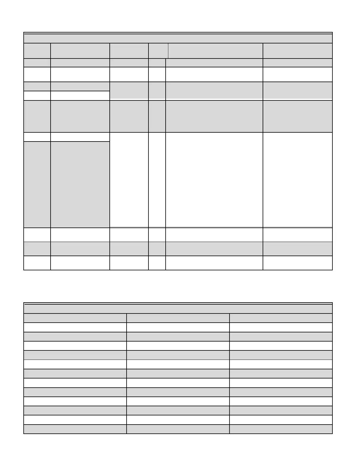
Figure 64 MODBUS Input Variables (Read Only)
4) The 4-20mA (0-10V) setpoint.
The maximum number of boilers available to
fire.
The system return temperature (if available).
See BoilerStatus4 to determine if the sensor
is present.
Boiler SystemFlow High (Upper) and Low
(Lower) 16 bit registers. To get Boiler
SystemFlow High (Upper) and Low (Lower)
16 bit registers. To get the actual
SystemFlow, the high and low 16 bit
registers must be combined (concatenated)
into a single 32 bit counter as:
SystemFlowHigh16: SystemFlowLow16
Example
SystemFlow = ((SystemFlowHigh16 * 65536)
+ SystemFlowLow16) * 0.01
This value is either the system flow meter
reading or the value written to the
BMSFlowRateGPM register by the BMS.
The number of boilers currently running for
heating.
The number of boilers currently running for
DHW.
The number of boilers currently running due
to a local override, T1, T2, AA/High Fire, etc.
Figure 65 MODBUS — BoilerStatus Flags
Header Sensor not Detected
0 = detected, 1 = not detected
Supply Sensor not Detected
0 = detected, 1 = not detected
Return Sensor not Detected
0 = detected, 1 = not detected
Outside Sensor not Detected
0 = detected, 1 = not detected
 Loading...
