Figure 16
CAUTION: Unbalanced blades cause
excessive vibration and eventual
damage to unit. Balance blades before
reinstalling on unit.
Never weld or straighten blades.
Install Blades
CAUTION: Mating surfaces between
spindle, lower spindle, guard, blade,
and washer MUST be free of debris to
ensure correct tightness and alignment.
See Figure 15.
1. Secure lower spindle guards and blades
to
spindles with one bevel washer and hex
bolt. Torque to 156 N•m – 217 N•m
(115 lb-ft – 160 lb-ft).
2. Reconnect spark plug wires.
CHECK BATTERY
WARNING: Avoid Injury.
Battery posts, terminals and related
accessories contain lead and lead
compounds, chemicals known to the
State of California to cause cancer and
reproductive harm. Wash hands after
handling.
Remove Battery
Remove Factory Battery
1. Place unit in service position. See Service
Position on page 17.
2. Disconnect the negative cable and then
the
positive cable from battery.
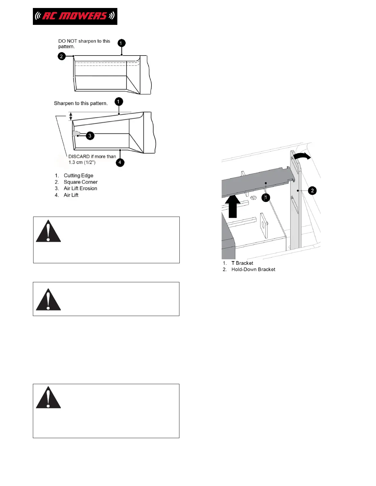
3. Loosen hex nut securing right hold-down
bracket to frame.
4. Remove T bracket from lower slots in hold-
down bracket. (See Figure 17.)
5. Remove battery.
Figure 17
Remove U1 Battery
1. Place unit in service position. See Service
Position on page 17.
2. Disconnect the negative cable and then
the
positive cable from battery.
3. Loosen hex nut securing right hold-down
bracket to frame.
4. Remove T-bracket from upper slots in hold-
down bracket. Retain for reinstallation.
5. Remove battery.
Clean Battery
1. Clean terminals and battery cable ends
with
a wire brush.
2. Coat terminals with dielectric grease or
petroleum jelly.
20