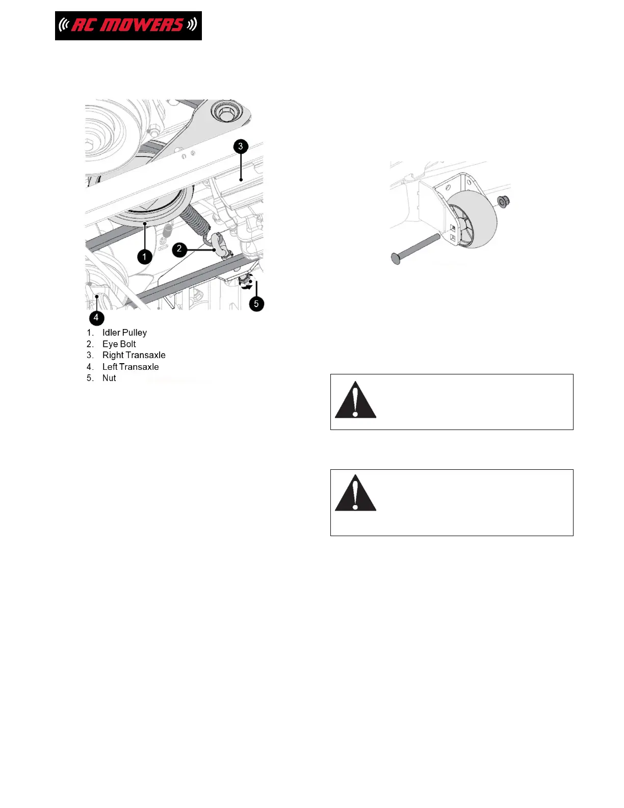
IMPORTANT: Make sure belt has tension and
is
aligned in all pulleys.
Figure 39
4. Reinstall clutch stop and mounting
hardware. (See Figure 38.)
5. Reinstall clutch stop bracket and secure
with original hardware. (See Figure 39.)
6. Return hood to operating position.
7. Reinstall PTO belt. See Install PTO Belt on
page 27.
8. Reinstall transaxle skid and secure with
original hardware. (See Figure 35.)
ADJUST ANTI-SCALP WHEELS
See Figure 40.
The anti-scalp wheels are set at the factory
for
typical mowing height, but can be adjusted
for high or
low cutting conditions.
1. Stop engine, remove key and wait for
moving parts to stop and for hot parts to
cool.
2. Remove hardware securing anti-scalp
wheels to deck and remove wheels.
3. Position wheels as necessary:
•
For a very high cutting height, set the
anti-scalp wheels in the lowest position
on the bracket.
•
For a very low cutting height, set the
anti-scalp wheels in the highest position
on the bracket.
4. Secure with original hardware.
IMPORTANT: All anti-scalp wheels MUST be
set to
the same height.
Figure 40
REMOVE / INSTALL MOWER DECK
Remove Deck
1. Place unit in service position. See Service
Position on page 17.
WARNING: Avoid Injury
Springs store energy. Keep body parts
away from pinch points when removing
the deck.
2. Remove PTO belt from clutch. See Remove
PTO Belt on page 25.
WARNING: Avoid Injury
Mower lift arms and lift pedal could
cause severe injury if the lift-assist
springs are not disconnected before the
lift links.
3. Push deck lift arm completely forward to
engage transport lock.
4. Position supports such as blocks or jack
stands under each side of the deck.
5. Release transport lock and slowly lower
deck until it rests on supports.
6. Slowly disconnect lift-assist springs from
spring peg on each side of deck. (See
Figure 41.)
29