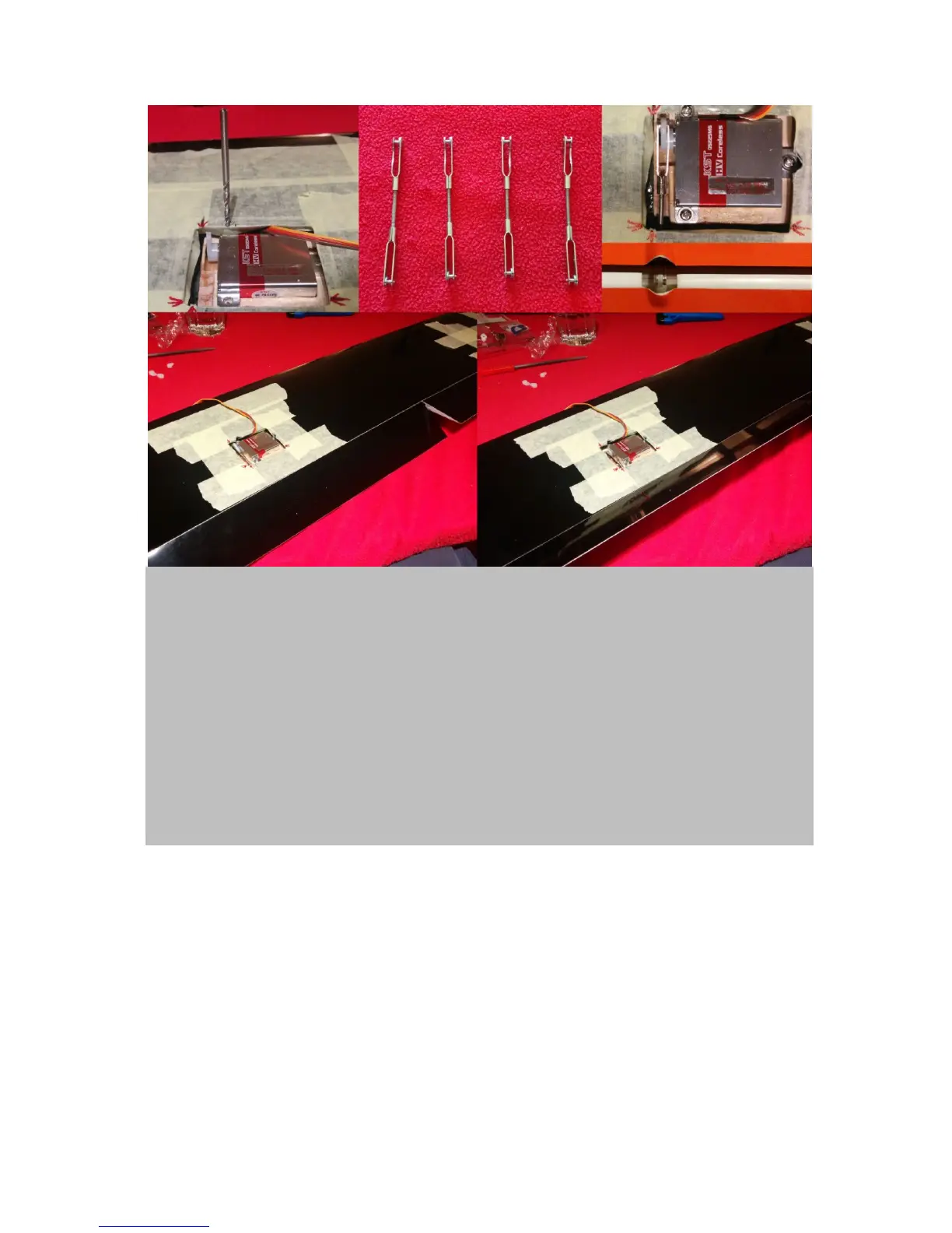
Figure 9. Adjust the ail and flap linkage systems: Fix the wing servos with the appropriate screws.
Therefore, you first might need to grind off a little from the surrounding wing (upper left & right). Next
screw the clevises onto the supplied metal threaded rods to create pushrods (upper middle panel). Now
they need to be adjusted. Flaps: Connect the respective servo to your receiver(+battery). Switch on your
transmitter and choose a “clean channel” by creating a “new model” setup without any pre-settings. Install
the servo horn in a 30˚ forward angle (upper right). This will allow for extreme positive (downward)
movement of the flap, as needed for airbrake. Next, fiddle in the respective pushrod through the hole in the
shear web and connect to the servo horn (upper right). Remember that one clevis has a grinded side, which
needs to face the servo horn base. Now, adjust the pushrod’s length so that upon connection to the control
horn (middle, right) the flap is in strak (in perfect alignment with the normal profile). Go about it the exact
same way for the ails, except that you mount the servo horn in a straight position, because here pretty much
equal +/- movements can be desired. Test both flaps and ails. Flaps need a maximum deflection of about 30-
45˚ +/- (lower panels) and flaps around 80˚positive and only 30˚ negativ. Finally, make sure again flaps and
ails are in strak when connected to a clean channel. Finally, de-mount the push-rods as well as the servos
but keep the adjustments conserved.
As soon as your wing servos are mounted and you have adjusted the pushrods and sucessfully tested
the deflection levels of flaps and ails, its time solder the pushrods. This will help you to achieve
minimum tolerances. The next step also involves soldering. Prepare the wing cable trees and fiddle
them into the wings. Both tasks are explained in figure 10.