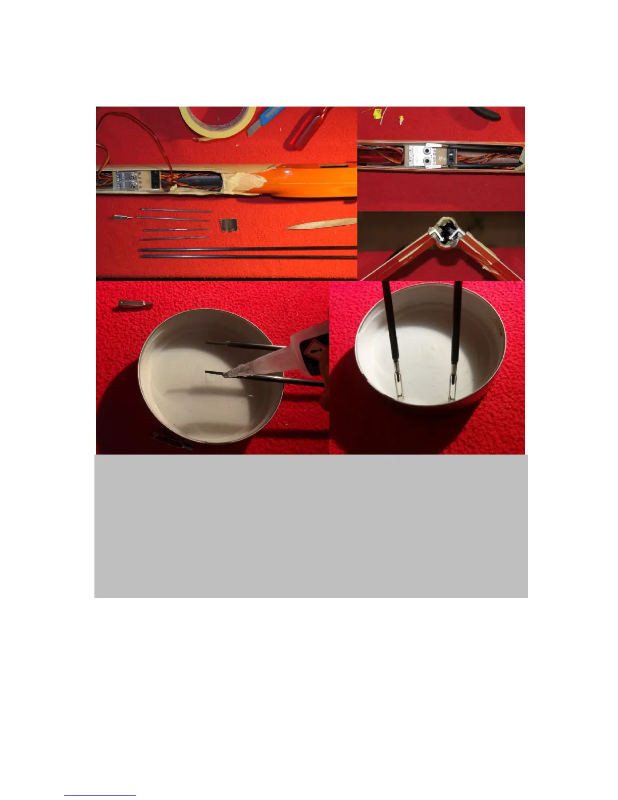
19
rods with clevises permanently connected, to get a close to zero tolerance linkage system. Figure 17
will guide you through that process.
Figure 17. V-Tail linkage: Upper left. Use the long carbon rods that are delivered with the kit (figure 1g).
Fiddle them into the fuselage. Servo horns need to be in 90˚ position to servos and V-tail control surfaces in
strak. Now mark each rod 4 cm in front of the respective V-tail linkage horn and 4cm behind the servo horn.
Take them out of the fuselage and cut at marks. Instead of the supplied threaded rods (figure 1b), I suggest
to use 1,5 mm carbon rods for the connection of the clevises. Cut the 1,5mm rods to four 10cm pieces
(upper left) and laminate those 7-8 cm deep into both sides of the thick carbon rods using UHU endfest. Let
cure over night. In the meanwhile, trim the clevises as seen for wing servo clevises in figure 6. Once epoxy
has cured, the clevises can be screwed onto the rods with force. To make it easier, you can grind off some
material from the end of the rods using glass paper. Now, adjust clevis positions so that the V-tail control
surfaces are perfectly in strak when the servos are in 90˚ positions (upper right). Permanently attach
clevises using cyanacrylacetate super glue (lower images). As soon as hardened you can mount the ready
made pushrods in the fuselage and you will be happy that there is close to zero tolerance on the V-tail.
Ballast tube
The wing as well as the fuselage servos and linkages are all mounted, so I suggest to install the
ballast tube in the fuselage. In figure 18 I describe how to mount it exactly in the CG.