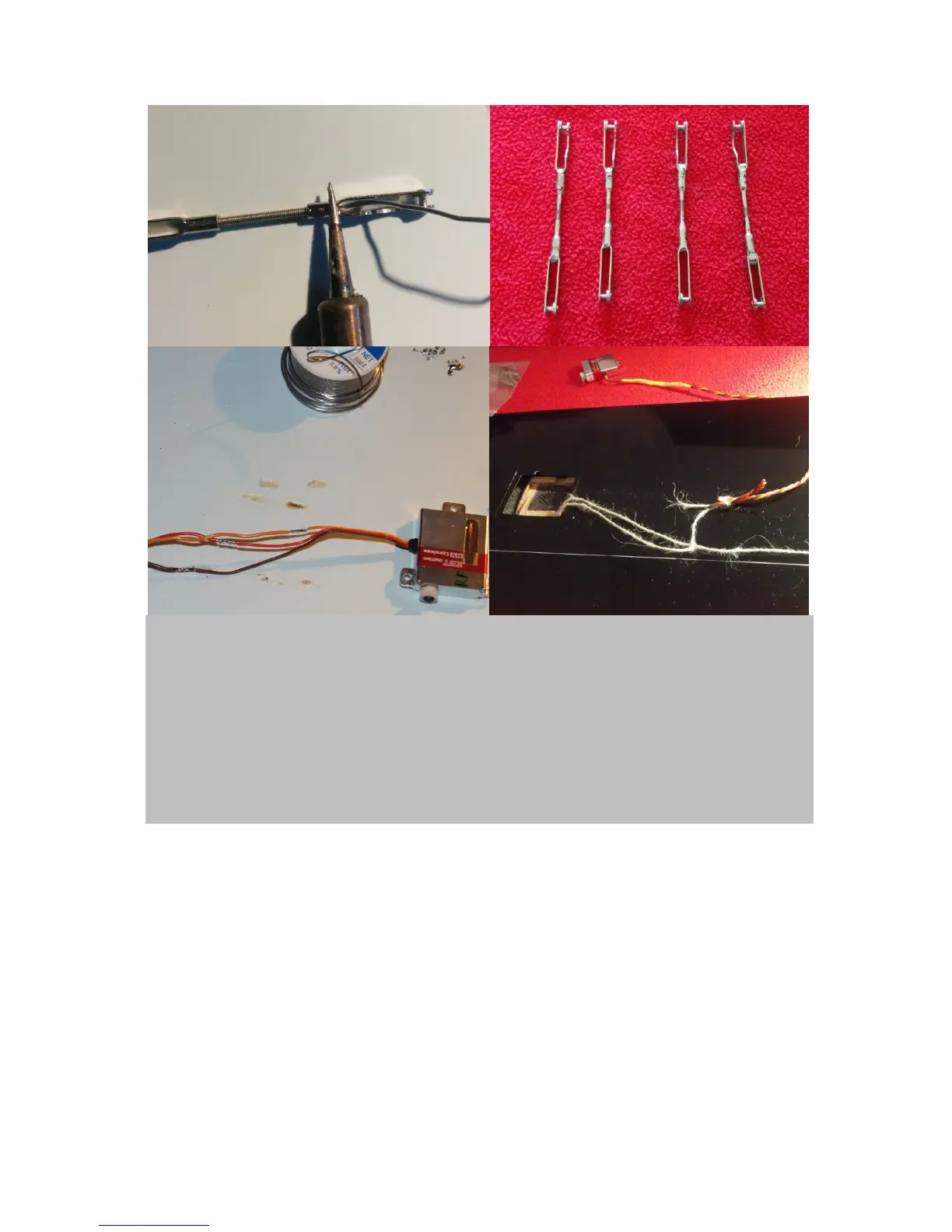
Figure 10. Soldering wing -pushrods and –cable trees: To ensure a tolerance free fit of your flap and ail
linkage systems it is advisable to permanently fix both clevises on either side of the threaded rod by using
super glue or, as shown here by soldering them (upper left). For the end result, see (upper right). While
you’re at soldering, I suggest to also prepare the wing cable trees. A conventional 3 x 0,34 qmm diameter
twisted servo cable will do perfectly for this job. Solder each of the four servos with a piece of cable long
enough to protrude 10cm out of the wing at the wing base. I simply cut the cables of the servos sequentially,
interspaced by 3cm and vice versa for the connector cables. This way I can solder them (lower left) and
subsequently cover them using just one heat shrink tubing (yellow, on top of lower right panel). Next, fiddle
any type of cord from the wing base to the servo bays using e.g. on fo the provided carbon tubes (figure 1g)
and a piece of tape to fix the cord to the tube. Next, you can knot the readily soldered servo cables to the
cord and pull each one through the wing.
Both, the flaps’ as well as the ails’ servo connector cables now need to be soldered to plugs to allow
for connetion to the fuselage. Green multiplex plugs are well suited for this. See figure 11.