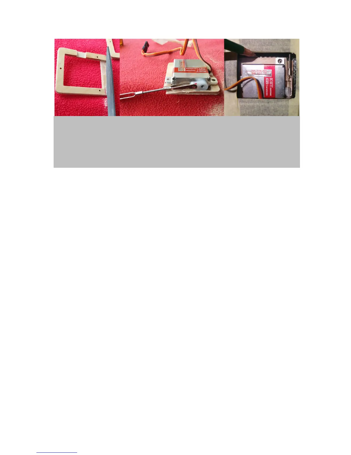
Figure 7. Prepare the servo frames: Mill down the servo horn side of each of the four servo frames (left
panel) to allow for full movement of the servo horns (middle). Check if full range of motion is allowed for
(middle). Test fit the servos in the servo bays (right). The front edge of the servo should be aligned with the
front edge of the servo bay. Fiddle in the pushrods through the holes in the shear webs and connect them to
the servo control horns in upright position. The servo should now be straight aligned and the pushrods need
to move freely while pointing exactly towards the wing control horns. If that is given mark the servo position
(right).
Next, you want to fix the wing servo frames in the marked positions using slow curing UHU endfest
epoxy. It is best to do this with the servos attached to the frames to find the exact positions.
Importantly, you will need to protect the servos from the epoxy to ensure that they are not getting
stuck for good in the wings. See figure 8.