Installation
3. Mark the hole positions. Drill and tap 2
holes M8 to attach the sensor bracket,
and 2 holes M6 in the lift arm for the
magnet bracket*.
* In some cases the magnet can be
mounted directly onto the lift arm but
you must fit a fibre washer between
the magnet and the arm.
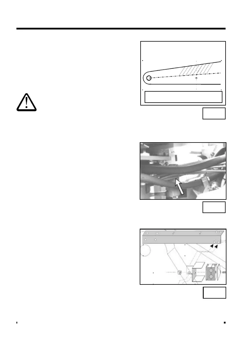
Do not drill the lift arm above the
center line (neutral axis) of the lift
arm ! (fig. 11)
4. Fit the brackets. Attach the magnet
using the stainless steel setscrew with
the fibre washer between the magnet
and mounting face.
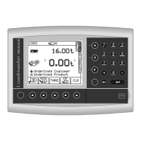
5. Route all cables through the conduit
provided in the kit. Cable tie the
conduit at 300mm (12") spacing
following where possible existing
pipework or cabling. You must pass
the conduit through the chassis pivot
point on articulated loaders (fig. 12).
Do not secure the cables to the
vehicle loom.
6 Assemble the reference and direction
clamp assembly as shown in figure 13.
The bracketing is designed so that the
assembly may be installed to either
side of the machine, by rotating the
angle bracket 90 degrees.
Remove the original M8 bolt from the
green Nylon Clamp, and replace it
with the longer M8 x 60 mm, Then
tighten with the sensors in the correct
position.
The clamp with sensors should then
be inserted into the clamp holder, and
tightened into position by using the
M8 nyloc nut supplied.
Fig. 12
Fig. 11
Do not drill above center line!
Fig. 13
Angle Bracket
Clamp Holder