14
2.2 HYDRAULIC CONNECTIONS | COLLEGAMENTI IDRAULICI
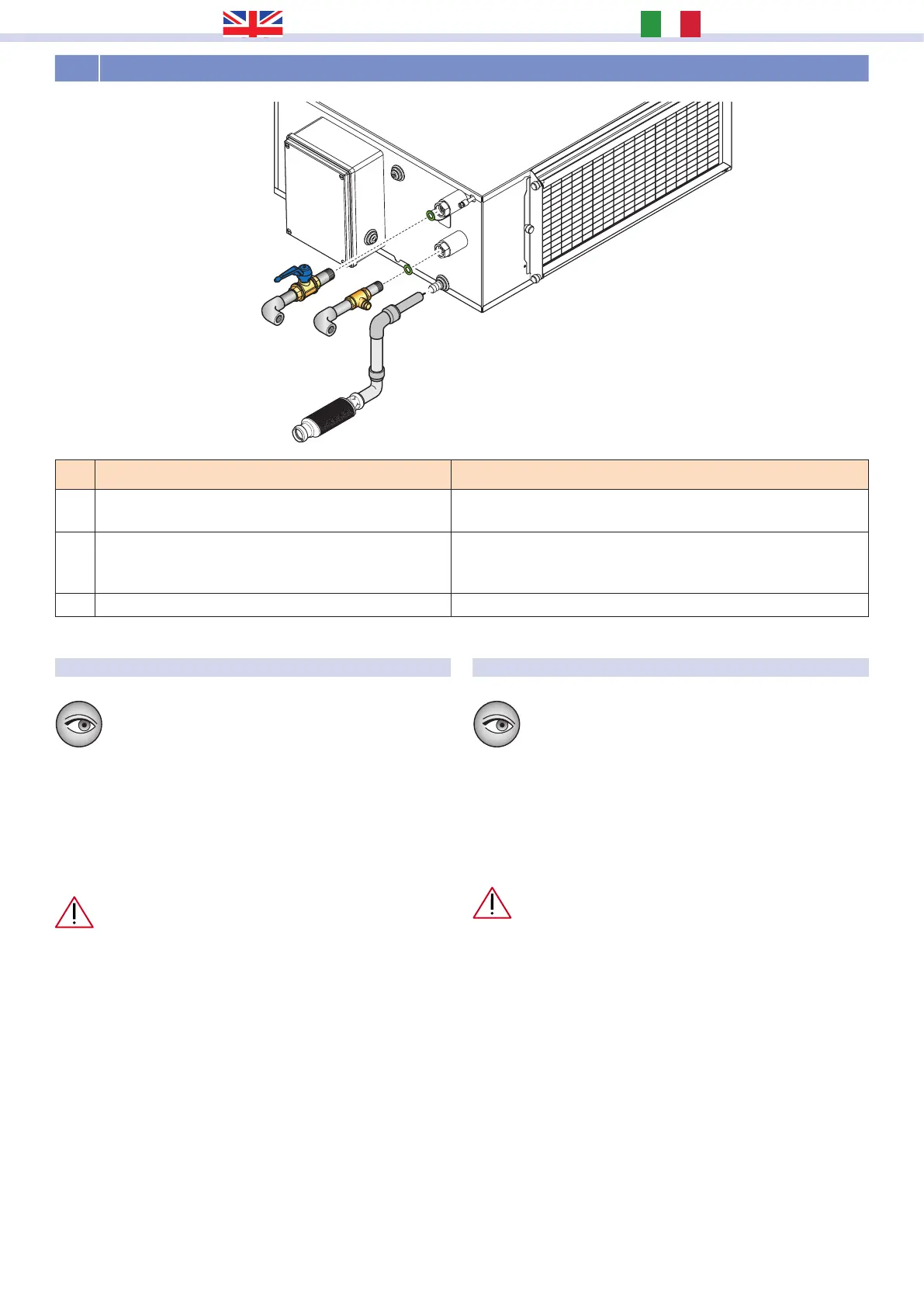
INSTALLAZIONE SCARICHI CONDENSACONDENSATION DRAIN INSTALLATION
A
B
C
Lo scarico condensa e le tubazioni di ingresso e
uscita devono rispondere alle norme e leggi vigenti
nel paese di utilizzo.
Il sistema di scarico (attacco portagomma Ø 14 mm) deve
prevedere un adeguato sifone, dimensionato per una portata
di 15 l/h e avente una pendenza minima, sia per consentire il
deusso della condensa in condizioni di possibile depressione,
sia per evitare l’ingresso di odori indesiderati.
È necessario realizzare il sifone sulla linea di scarico
utilizzando e scegliendo, in base alle esigenze, fra i
kit di scarico condensa RDZ disponibili (SF-P / SF-M
13). Rispettare, in base al modello scelto, le
indicazioni di installazione riportare di seguito.
• Il sifone non deve esser posizionato necessariamente sotto la
macchina ma può essere spostato lateralmente e posizionato
ad una quota comunque inferiore al raccordo di scarico
dell’unità.
• Il sifone deve potersi disconnettere facilmente dal punto di
scarico sulla macchina e/o sull’accessorio al ne di agevolare
eventuali manutenzioni. Adescare il sifone prima della messa
in servizio.
• Assicurarsi che il tubo per il deusso della condensa non
solleciti l’attacco di scarico dell’unità.
• Lo scarico condensa dovrà essere adeguatamente supportato
e correttamente isolato se quest’ultimo passa attraverso
spazi non riscaldati (esempio verande esterne) per prevenire
il congelamento.
The condensation drain and the inlet and outlet pipes
must comply with the standards and laws in force in
the country of use.
The condensate pipeline (hose connector Ø 14 mm) shall be
provided with a syphon, considering a flowrate of 15 l/h and
minimum inclination, both to win the possible air underpressure
at outlet and to avoid the entry of bad smells.
It is necessary to make the siphons on drain line using
and choosing, as required, from the available RDZ
condensate drain kits (SF-P / SF-M 13). According to
the model chosen, respect the installation instructions
given below.
• Syphon shall be sized according to instructions on below gure.
It must not necessarily be positioned under the machine, but
can be moved laterally and always positioned lower than the
tting unit drain.
• It shall be possible to easily disconnect the syphon on the unit
and/or on the accessory in order to facilitate possible services;
prime syphon before starting up.
• Check that pipeline doesn’t stress condensate outlet connection.
• The condensate drain system should be adequately supported
and suitably insulated if it passes through unheated spaces and
voids (e.g. loft spaces) to prevent freezing.
Rif. Description Descrizione
A
Pre-treatment water outlet (1/2” F) with cut-o valve to
adjust ow rate
Uscita acqua pre-trattamento (1/2” F) con valvola di intercettazione
per regolazione portata
B
Pre-treatment water inlet (1/2” F) with lockshield to adjust
ow rate It is recommended to install metering units
to control the water ow rate.
Ingresso acqua pre-trattam. (1/2” F) con detentore di regolazione
portata Si consiglia di installare i relativi misuratori di portata
per il controllo del usso dell’acqua.
C Hose connector Ø 14 mm drain for unit condensation Scarico portagomma Ø 14 mm per condensa