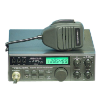
GENERAL
1.
Frequency Range
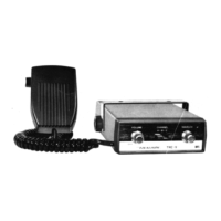
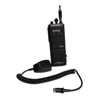
2. Microphone
3.
Speaker
4.
Antenna Connector
5.
Jacks & Connectors
6.
Controls
7.
Display/Indicators LCD
LED
8.
Size
9.
Weight
1
0. Accessories
11
. Power Source
MEASUREMENT CONDITIONS
1. Power Source
2. Antenna Impedance
·3. Test Temperature
SPECIFICATIONS
28.0000
""29.6999
MHz
600
Q,
Dynamic Type
8Q,5W
MType
MIC (8 PIN), DC Power (3 PIN),
EXT
SP
(3.5~),
CW
Key
IN
(3.5~),
Phone
(3.5~)
Mode selector (SSB/CW),
ON/OFF
Volume, Squelch, RF
Gain, Power
HI/LOW Switch, RIT, NB ON/OFF Switch,
Frequency
Dial, FreQuency/Memory UP/DOWN SW,
Store Key, 500 k Key, MEMO key, Step Key,
F.
LOCK
Switch,
TX/RX
Switch
Frequency Indicator, Memory
Channel Indicator, Mode In-
dicator (CW/SSB) MEMO, TX Indicator
. RF/S Meter
2-
7
/
16
"(H) X
7-
9
/
32
"(W) X
7_7/
8
"(0)/
62 mm(H) x 185 mm(W) x 200 mm(D) (Unit)
4 lbs 3 oz (1.9 kgs) (Unit)
DC -Power Cable with Fuse
Microphone with UP/DOWN
SW
Mic Hanger
13.8 V
DC +
15/-20
o/o,
Negative Ground
13.8 V
(DC)
50Q
4.
SSB Modulation Frequency, Two Tone: 500 Hz &
2400Hz
5.
Mean Signal Input Level
6. Reference Audio Output Power
7. Audio Frequency
8.
Audio Output Load
SSB
cw
1000
j,tV
0.5W
1kHz
800Hz
8 Q Resistive
-2-