RF
Amp
Alignment
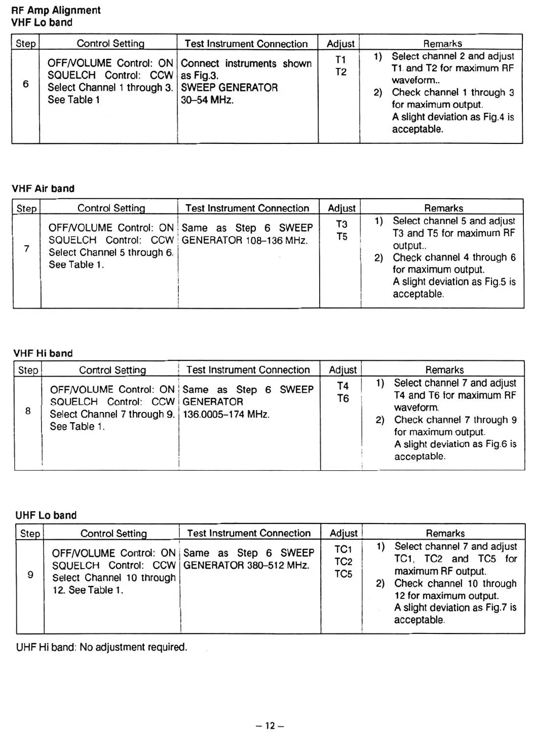
VHF Lo band
Step
Control Settina
Test Instrument Connection
Adiust Remarks
T1
1)
Select channel 2 and adjust
OFFNOLUME Control: ON
Connect instruments shown
T2
T1.and T2 tor maximum RF
SQUELCH Control:
CCW as Fig.3.
wavetorm..
6
Select Channel 1 through 3.
SWEEP GENERATOR
2) Check channel 1 through 3
See Table 1
30-54 MHz.
tor maximum output.
A slight deviation as Fig.4 is
acceptable.
VHF
Air
band
Step
Control Settina
1 Test Instrument Connection
Adiust j
Remarks
I
T3
I
1) Select channel 5 and adjust
OFFNOLUME Control : ON ! Same as Step 6 SWEEP
T5
T3 and T5 tor maximum RF
SQUELCH Contral: CCW ! GENERATOR 108-136 MHz.
i
i
output..
7
Select Channel 5 through 6. 1 .
I
2)
Check channel 4 thraugh 6
See Table 1.
!
I
tor maximum output.
I
A slight deviation as Fig.5 is
I
I
acceptable.
!
I
VHF H' b d
I an
Step Control Setting
! Test Instrument Connection
Adlust Remarks
.
T4
I
1)
Select channel 7 and adjust
OFFNOLUME Contral: ON
lSame as Step
6
SWEEP
T6
T4 and T6 tor maximum RF
SQUELCH Control: CCW
I GENERATOR !
wavetorm.
8
Select Channel 7 through 9. 136.0005-174 MHz.
2)
Check channel 7 through
9
See Table 1.
tor maximum output.
A slight deviation as Fig.6 is
i
acceptable.
,
UHF Lo band
Step Control Setting Test Instrument Connection
Adiust
Remarks
!
TC1 I
1)
Select channel 7 and adjust
OFFNOLUME Control: ON
iSame as Step 6 SWEEP
TC1, TC2 and TC5 tor
SQUELCH Control : CCW GENERATOR 380-512 MHz.
TC2
I
maximum RF output.
TC5
9
Select Channel 10 through
2)
Check channel 10 through
12. See Table
1.
12 tor maximum output.
A slight deviation as Fig.7 is
acceptable.
I
UHF Hi band : No adjustment required.
- 1
2-
 Loading...